Mostrando entradas con la etiqueta #1. Mostrar todas las entradas

lunes, 3 de enero de 2011

Launch campaign, first launch

English
In our wiki-space campaign we have decided the first launch date, this is the next January 28th. For this launch the following objectives:

    1. Launch a stratospheric balloon with our launch ramp and the system arrives at least 30 km.
    2. At 30 km high, launch a rocket stage with a monitoring system.
    3. At 2 km to open a parachute.
    4. See the results, analyze and report.

Then you can see the code that we will introduce the AWIP to the igniter is turned on at 30 km and the parachute at 2 km. This has been done by Juan Martínez and Joshua Tristancho and reviewed by Victor Kravchenko.


Castellano
En nuestra wiki-campaña espacial nos hemos propuesto la primera fecha de lanzamiento, esta es el 28 de enero. Para este lanzamiento los objetivos son los siguientes:
  1. Lanzar nuestro globo estratosferico con nuestra rampa le lanzamiento y que llegue a un mínimo de 30 km.
  2. A 30 km lanzar la etapa del cohete con un sistema de seguimiento.
  3. A 2 km que se abra un paracaídas.
  4. Ver los resultados, analizarlos y reportarlos.
Seguidamente podes ver el código que le vamos a introducir a la AWIP para que que el igniter se encienda a 30 km y el paracaídas a 2 km. Este ha sido hecho por Juan Martínez y Joshua Tristancho y revisado por Victor Kravchenko.


Code (codigo):


#include <Wire.h>
#include <SoftwareSerial.h>
#include <EEPROM.h>
#include <math.h>
#define IGNITION_ALTITUDE 30000 // Above this altitude in meters the igniter is activated
#define PARACHUTE_ALTITUDE 2000 // Below this altitude in meters the parachute is deployed
#define SAFETY_ALTITUDE 3000 // Safety altitude above wich the parachute can be deployed
#define APOGEE_ADDR 0 // Apogee EEPROM Address
#define IGNITION_PIN 12 // Ouput pin number to activate the igniter 5V
#define PARACHUTE_PIN 10 // Ouput pin number to activate the parachute 5V
#define GPSRX_PIN 11 // Input pin for GPS Rx serial port
#define GPSTX_PIN 13 // Output pin for GPS Tx serial port
//#include "itg3200.h" // GYRO ITG-3200
#define GyroID B1101001
//Register 22 - FS_SEL, DLPF_CFG
#define R22 0x16
#define R22INIT B00011011
//Register 62 - Power Management
#define R62 0x3e
#define R62INIT B00000001
//Registers 27 to 34 - Sensor Registers
#define TempH 0x1b
#define TempL 0x1c
#define GyroXH 0x1d
#define GyroXL 0x1e
#define GyroYH 0x1f
#define GyroYL 0x20
#define GyroZH 0x21
#define GyroZL 0x22
//#include "lis331hh.h" Accelerometer LIS331HH
#define AccID 0x18
//Register CTRL_REG0 - Power management and conf
#define RCTR0 0x20
#define RCTR0INIT B00100111
//Sensor Registers
#define AccXH 0x29
#define AccXL 0x28
#define AccYH 0x2B
#define AccYL 0x2A
#define AccZH 0x2D
#define AccZL 0x2C
#define AccStat 0x27
void i2cSetRegister(int device, int address, int value)
{
  Wire.beginTransmission(device);
  Wire.send(address);
  Wire.send(value);
  Wire.endTransmission();
}
byte i2cGetRegister(int device, int address)
{
  Wire.beginTransmission(device);
  Wire.send(address);
  Wire.endTransmission();
  Wire.requestFrom(device, 1);
  if(Wire.available())
  return Wire.receive();
  return B00000000;
}
int i2cGetValue(int device, int addressH, int addressL)
{
  return i2cGetRegister(device, addressH) * 256 + i2cGetRegister(device, addressL);
}
// Globals
SoftwareSerial GPS = SoftwareSerial(GPSRX_PIN,GPSTX_PIN);
int addr;
int val; // Last byte read from GPS
float alt; // Last altitude read from GPS
float apogee; // Highest altitude read from GPS. This variable is mirrored in EEPROM.
byte k[]={0,0,0,0,0,0,0,0,0,0,0,0,0}; // Read buffer for GPS input
float EEPROMGetFloat(int addr)
{
  float num;
  ((byte*)&num)[0]=EEPROM.read(addr++);
  ((byte*)&num)[1]=EEPROM.read(addr++);
  ((byte*)&num)[2]=EEPROM.read(addr++);
  ((byte*)&num)[3]=EEPROM.read(addr++);
  return num;
}
void EEPROMSetFloat(int addr, float num)
{
  EEPROM.write(addr++,((byte*)&num)[0]);
  EEPROM.write(addr++,((byte*)&num)[1]);
  EEPROM.write(addr++,((byte*)&num)[2]);
  EEPROM.write(addr++,((byte*)&num)[3]);
}
byte Next()
{
  // BYTE, BIN, OCT, HEX, 1 = number of decimals
  val=byte(GPS.read());
  Serial.print(val,BYTE); // For debbuging purpose only
  return val;
}
int ReadParam(byte chr=',')
{
  int i=0;
  while(true)
    if(i>=sizeof(k))
      return -1; // Buffer overrun
    else if((k[i]=Next())==chr)
      return i; // Read 'i' bytes
    else
      i++;
}
void setup ()
{
  pinMode(IGNITION_PIN,OUTPUT);
  digitalWrite(IGNITION_PIN,LOW);
  pinMode(PARACHUTE_PIN,OUTPUT);
  digitalWrite(PARACHUTE_PIN,LOW);
  GPS.begin(4800);
  Serial.begin(4800);
 
  // EEPROM dumping
  /*
  for(addr=0;addr<512;addr++)
  {
    if (!(addr%16)){Serial.println();Serial.print(addr/1000.0f,3);Serial.print(": ");}
    Serial.print(EEPROM.read(addr)/1000.0f,3);Serial.print(" ");
    //EEPROM.write(addr,0); // WARNING: This line will erase all the EEPROM memory
  }
  Serial.println();
  */
 
  addr=0;
  val=0;
  alt=0;
  apogee=EEPROMGetFloat(APOGEE_ADDR);
  Wire.begin();
  // Hyperterminal at 57600 and Arduino at 115200 bauds
  //Serial.begin(115200);
  // Accelerometer LIS331HH setup
  i2cSetRegister(AccID, RCTR0, RCTR0INIT);
  // Gyro ITG-3200 setup
  i2cSetRegister(GyroID, R62, R62INIT);
  i2cSetRegister(GyroID, R22, R22INIT);
  // Hardware-on-the-loop config
  //i=0;
}
void loop()
{
  int i;
  if(Next()=='$')if(Next()=='G')if(Next()=='P')if(Next()=='G')if(Next()=='G')if(Next()=='A')if(Next()==',')
  {
    if(ReadParam()>=0)      // Time in UTC of position
    if(ReadParam()>=0)      // Latitude of position
    if(ReadParam()>=0)      // Latitude N or S
    if(ReadParam()>=0)      // Longitude of position
    if(ReadParam()>=0)      // Longitude E or W
    if(ReadParam()>=0)      // GPS quality                            (0=fix not available, 1=Non-differential GPS fix available, 2=Differential GPS (WAAS) fix available, 6=Estimated)
    if(ReadParam()>=0)      // Number of satellites                   (00 to 12)
    if(ReadParam()>=0)      // Horizontal dilution of precision       (0.5 to 99.9)
    if(ReadParam()>0)       // Antenna altitude above mean sea level  (-9999.9 to 99999.9)
    {
      alt=atof((char*)&k[0]);
      if(ReadParam()>=0)    // Units of antenna altitude, meters      M
      if(ReadParam()>=0)    // Height of geoid above ellipsoid        (-999.9 to 9999.9)
      if(ReadParam()>=0)    // Units of geoid height, meters          M
      if(ReadParam()>=0)    // Age of differential GPS data, seconds  Null
      if(ReadParam('*')>=0) // Differential reference station ID      Null
      if(ReadParam(10)>0)   // Checksum                               *HH
      {
        if(alt>apogee)
        {
          apogee=alt;
          EEPROMSetFloat(APOGEE_ADDR,alt);
        }
        if(alt>IGNITION_ALTITUDE)digitalWrite(IGNITION_PIN,HIGH);
        if(alt<PARACHUTE_ALTITUDE)if(apogee>SAFETY_ALTITUDE)digitalWrite(PARACHUTE_PIN,HIGH);
      }
    }
  }
}
miércoles, 3 de noviembre de 2010

Igniter & noozle test (Stage2 first burn)


English
In the last test we did the igniter decided to change the mode coupling the igniter with cable. In the other test we did was hook up the igniter "bare" (just the powder-filled bulb) inside the engine, seen the problems and the time it cost us to connect the cable to the igniter when to launch, we came up with the igniter with a 15 cm cable soldered to a connector at the other end, so we save time in preparation for takeoff, that we can release the igniter while we are trying to plug the cable into the rocket motor and cable as the cable is attached to the rocket burn, so it's better than blowing a 15-cm cable that does not have to go cutting a 150 cm. So we have a soldier igniter cord of 15 cm and epoxied to a motor amateur (for when we try) ready to be assembled in a rocket to be launched.

Test: Testing the "new" igniter, an amateur engine support for both tests and test a prototype nozzle. To this is to use a standard steel support where we are going to make a hole to pass the engine and we will weld a bracket to hold the can and it does not move, then we'll screw it to the ground (if case).


Test result: The igniter works perfectly, the engine is on and on for about 3 seconds, the can has a deformation.

Conclusions: At first we thought that the narrowing was an inplotion but later saw that no, due to heating of the can and push the nozzle, this is the shape of the can, in principle this is not a bad result because it shows that the nozzle works. The next step is to measure the nozzle thrust, that we'll make getting a hydraulic jack with a pressure sensor.


Castellano
En el último test que le hicimos al igniter decidimos cambiar el modo de acople del cable con el igniter. En los otros test lo que hacíamos era enganchar el igniter "pelado" (solo la bombilla llena de pólvora) en el interior del motor, vistos los problemas y el tiempo que nos costaba conectar el cable con el igniter a la hora de hacer el lanzamiento, se nos ocurrió crear el igniter con un cable de unos 15 cm ya soldado con un conector en el otro extremo, de esta manera nos ahorramos tiempo de preparación para el despegue, que se nos pueda desenganchar el igniter mientras estamos intentando conectar el cable dentro del motor del cohete y cable ya que el cable que va conectado al cohete se quema, así que es mejor que se queme un cable de 15 cm que no tener que ir cortando uno de 150 cm. Así pues tendremos un igniter soldado a un cable de 15 cm y pegado con resina a un motor amateur (para cuando hagamos pruebas) listo para ser ensamblado en un cohete y para ser lanzado.

Test: Probar el "nuevo" igniter, un soporte para motores amateur para hacer tests y a la vez probar un prototipo de tobera. Para esto se va a usar un soporte de acero estandarizado donde le vamos a hacer un agujero para que pase el motor y le vamos a soldar una abrazadera para sostener la lata y que no se mueva, luego vamos a atornillarlo al suelo (por si a caso)

Resultado del test: El igniter funciona perfectamente, el motor se enciende y esta encendido durante unos 3 segundos, la lata sufre una deformación.

Conclusiones: En un principio pensamos que el estrechamiento era una implosión pero que más tarde vimos que no, que debido al calentamiento de la lata y al empuje de la tobera, esta es la que deforma la lata, este en principio no es un mal resultado ya que nos demuestra que la tobera funciona. El siguiente paso es medir el empuje que nos da la tobera, esto lo vamos a conseguir poniendo un gato hidráulico con un sensor de presión.

Pictures (Fotos):

 Picture #1
 Picture #2
 Picture #3
 Picture #4
 Picture #5
 Picture #6
 Picture #7
Picture #8

martes, 2 de noviembre de 2010

Igniter test #2 (engine ignition)


English
Launch # 1 
Date: 10/29/1910 at 5:00 PM
Weather: clear sky, moderate wind from the East (E)
Location: Zaragoza.
Test: Test whether the igniter works with amateur rocket motor.

Production Stage: Use a can of soda from the elongated which removes the part where is the opening where you drink, your "ass" is asked a circular opening the diameter of amateur rocket motor, within the same is placed beside the glass hemisphere is not just a candle poses a well known multinational company, this is pasted with epoxy resin using a mold made with another can of soda the same diameter. Resin is applied twice, once dry, the excess is removed by the lathe and a radio to make it more aerodynamic. The engine is stuck in the hole with epoxy resin and fiber.


Material: Rocket consisting of a soda can and a spherical crystal with overall dimensions of 57.6 x 169 mm and an engine model weco D7-3, an igniter, a PVC tube of 68 mm x 1m hole in lid with First, electrical cable of at least 1.5 m, 9-volt battery, connector 9-volt battery, a tester and tweezers.


Procedure (check list):This procedure is going to "check" each time before launch.

  • Check if the igniter is continuous.
  • Place the igniter within the amateur rocket motor.
  • Paste the igniter with epoxy resin, not to put resin on top, one in the ass.
  • Pass the cable through the hole in the PVC cap.
  • Connect to the igniter end of the party that runs inside the PVC pipe.
  • Carefully insert the rocket by sliding to the bottom as you stretch the cable so there is no cable inside, under any circumstances enter the rocket pulling the cord.
  • Insert the connector to the battery of 9 V.
  • Turn ground cameras.
  • Check if you have seen continuous cable.
  • Place the vertical tube resting on the ground.
  • Turn on the camera tube.
  • Connect the 9 V battery

Test result: OK. The igniter worked perfectly, the stage lit shot out of the tube upward bending due to wind. When approaching its peak stage start making loops until it begins to fall in a straight line, this shows that the stage has a pretty good stability.


Castellano
Lanzamiento #1
Fecha y hora: 29/10/10 a las 17:00 horas
Condiciones del lanzamiento: Cielo totalmente despejado, viento moderado de componente Este (E)
Localización: Zaragoza.
Test: Probar si funciona el igniter con un motor de cohete amateur.

Fabricación de la etapa:  Se usa una lata de refresco de las alargadas en las que se quita la parte donde esta la abertura por donde se bebe, en el culo se le hace una apertura circular del diámetro del motor de cohete amateur, en ese mismo lado se le pone la semiesfera de cristal que no es más que un posa velas de una conocidisima multinacional, esta se pega con resina epoxy mediante un molde hecho con otra lata de refresco del mismo diámetro. Se le aplica resina dos veces, una vez seco se quita el exceso mediante el torno y una radial para hacerlo más aerodinámico. El motor se pega en el agujero con resina epoxy y fibra.

Material: Cohete formado por una lata de refresco y un cristal semiesferico con unas medidas totales de 57,6 x 169 mm y un motor weco modelo D7-3, un igniter, un tubo de PVC de 68 mm x 1m con tapa con agujero en un lado, cable electrico de mínimo 1,5 m, pila de 9 voltios, conector para pila de 9 voltios, un tester y unas pinzas.

Procedimiento (check list):
Este procedimiento lo vamos a "chequear" cada vez antes de realizar el lanzamiento.
  • Comprobar si el igniter tiene continua.
  • Poner el igniter dentro del motor de cohete amateur.
  • Pegar el igniter con resina epoxy, no poner resina en la punta, solo en el culo.
  • Pasar el cable por el agujero de la tapa de PVC.
  • Conectar con el igniter el extremo de la parte que pasa por dentro del tubo de PVC.
  • Insertar cuidadosamente el cohete haciéndolo deslizar hacia el fondo mientras se estira el cable para que no quede cable dentro, bajo ninguna circunstancia entrar el cohete estirando del cable.
  • Insertar el conector para la pila de 9 V.
  • Encender camaras de tierra.
  • Comprobar por última vez si hay continua en el cable. 
  • Colocar el tubo vertical apoyado sobre el suelo.
  • Encender la camara del tubo.
  • Conectar la pila de 9 V.

    Resultado del test: OK. El igniter funcionó perfectamente, encendió la etapa que salió disparada del tubo hacia arriba inclinándose debido al viento. Cuando se acerca a su apogeo la etapa empieza a hacer loopings hasta que empieza a caer en linea recta, esto nos demuestra que la etapa goza de una estabilidad bastante buena.

    Pictues (Fotos):

    Picture #1
     Picture #2
     Picture #3
     Picture #4
    Picture #5

    miércoles, 27 de octubre de 2010

    Igniter manufacturing & test #1

    Amateur igniter
    English
    Igniter
    An igniter is a device that typically contains pyrotechnic material (or flammable) and used to ignite other materials more difficult to ignite (ignite) or dangerous such as thermite (aluminum pyrotechnic composition and a metal oxide) gas generator or rocket solid fuel.

    Igniter Making: The igniter as a light bulb produce 1.5 volts. This side is cut and filled with gunpowder and covered with resin. (see the first movie)

    Igniter Operation: When short-circuit the battery, the igniter operates and increases the temperature by a few tenths of a second, heat + gunpowder result in a small explosion enough to ignite our propellant. (see the second movie)


    Castellano
    Igniter
    Un igniter es un dispsitivo que suele contener material pirotecnico (o inflamable) y se usa para prender otros materiales más dificiles de prender (ignite) o peligrosos como por ejemplo termita (composición pirotécnica de aluminio y un oxido metálico), generadores de gas o cohetes de combustible solido.

    Fabricación del Igniter: El igniter lo fabricamos con una pequeña bombilla de 1,5 voltios. A esta se le corta un lateral y se llena con polvora y se tapa con resina. (ver el primer video)

    Funcionamiento del Igniter: Al cortocircuitar la pila, el igniter explota y aumenta la temperatura por unas decimas de segundo, calor + polvora dan como resultado una pequeña explosión suficiente para prender nuestro propelante. (ver el segundo video)

    Pictures (Fotos):

    Picture #1
    Igniters
    Picture #2
    Igniters
    Picture #3
    Igniteres
    Picture #4
    Safety "Box"
    "Caja" de seguridad
    Picture #5
    Coninuity Checking
    Probando si hay continuidad


    Picture #6
    Ready to be ignited
    A punto para ser encendido


    Picture #7
    Igniter with more gunpowder
    Igniter con más polvora

    domingo, 10 de octubre de 2010

    Test #1: Preassure & behavior test

    English
    On tuesday we (Joshua & me) decide to do a preasure test and behavio of PVC pipe with attached latex balloon. It will be called test #1and consist of the following:

    Test #1: Make sure the PVC pipe can withstand the high pressures that will be submitted as you move up and see the behavior of the balloon to swell (see if it holds subject, if the union loses air, etc. ).

    Preparation Test #1: Seal the open end of PVC pipe with a stopper (also PVC), this cap is coupled to a plug connector for compressed air hoses, sealed and secured with epoxy resin. (picture #2)
    It dries in minutes and is completely seated within 3 days, in our case it isn't necessary to wait so long.Once dry the adhesive, is necessary to put the cap on the other end of the tube with a silicone adhesive and let allowed to dry several hours (Picture #3, 4 & 5). Once dry, proceed to place the tube upright because doing so will more faithfully reproduce the process that would continue the balloon-PVCpipe system, if it was "released", as attached to a table by heat (either prune used duct tape, etc) and a clamp. (Picture #6)
    Finally we add the connectors (PVC pipe) and female from the compressor.Place a wood protection (picture #7 & 8) to protect us in case we get to have high pressures in the balloon-PVCpipe system and can cause some type of release (eg PVC cap)

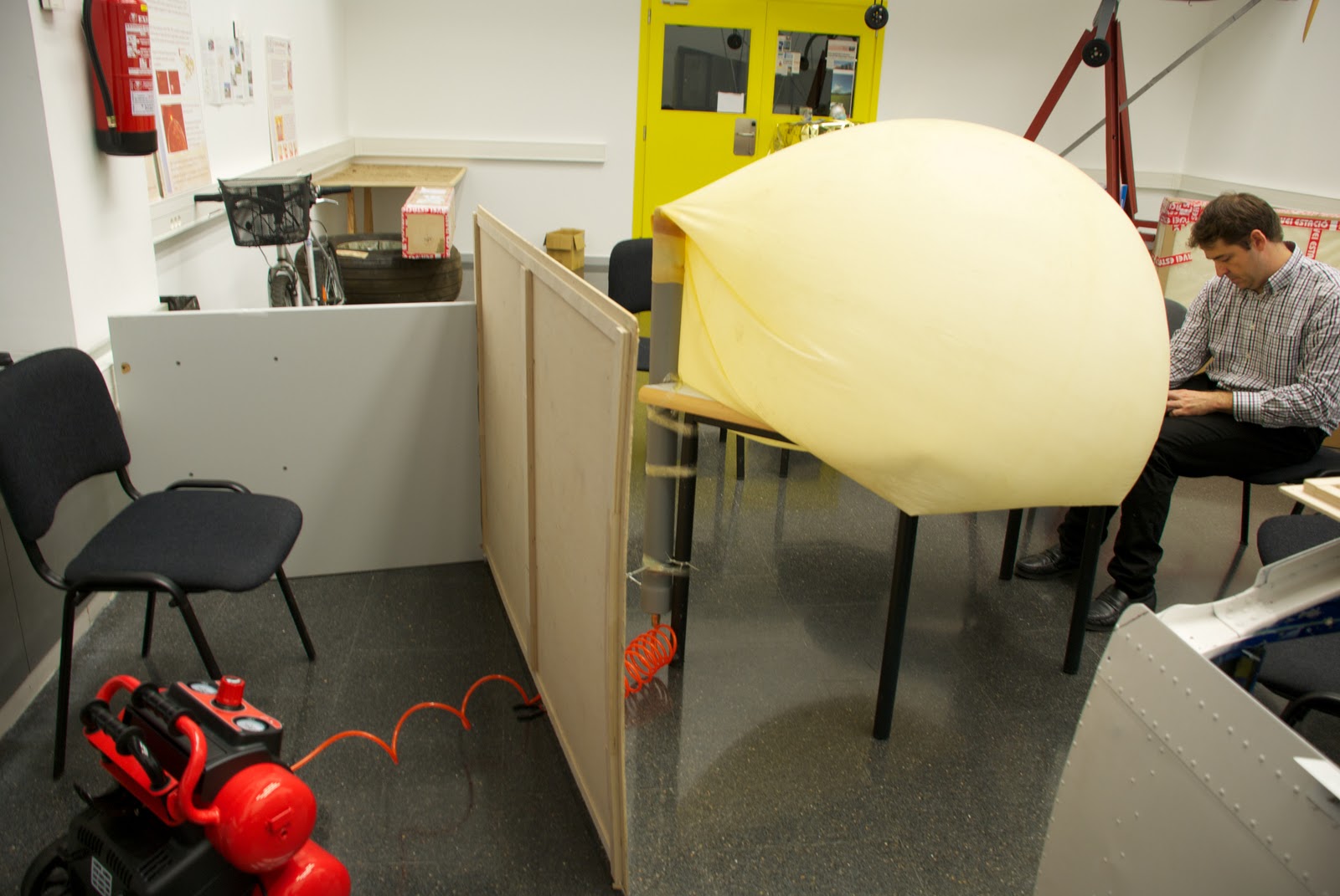
    Playing Test #2: We started to use compressed air and see how the balloon begins to swell. when this begins to have a considerable volume, tables and chairs are put under in order to hold up the tube as if the embers rise (this is, again, to play the position would have the balloon with PVC pipe), after a good while introducing air, desist. We conclude that our compressor is not powerful enough to give the pressure-flow we need. We then proceed to see the behavior of the inflated balloon. (Picture #9, 10 & 11)


    Test # 2 Result: FAILED test pressure due to the compressor. As far as the behavioral test we referred to some conclusions, the first is that it did not put the pipe with the noozle of the balloon and was a bit crooked (Picture #12), this is not a serious incident as probably only give us an inclination to the PVC pipe, but if this is likely to stay very crooked that compromised the properties of the balloon (that can exploit at an inappropriate height). The second conclusion we draw is that the nozzle PVC balloon air is not lost and with a simple clamp (only for extreme caution) this would be perfectly capable of supporting the weight of the PVC pipe over the payload.


    Castellano
    El martes decidimos (Joshua y yo) hacer un test de presión y comportamiento del tubo de PVC con el globo de látex "acoplado". Este se llamará test #1 y constará de lo siguiente:

    Test #1: Comprobar que el tubo de PVC es capaz de soportar las altas presiones a las que será sometido a medida que ascienda y ver el comportamiento del globo al hincharse (esto es ver si se aguanta sujeto, si pierde aire por la unión, etc.).

    Preparación Test #1: Sellar el extremo abierto del tubo de PVC con un tapón (también de PVC), a este tapón se le acoplará un conector macho para mangueras de aire comprimido, sellado y sujetado con resina epoxy. (picture #2)
    Esta se seca en cuestión de minutos y se asienta totalmente a los 3 días, en nuestro caso no será necesario esperar tanto tiempo.
    Una vez seco el adhesivo se procede a poner el tapón en el otro extremo del tubo mediante un adhesivo de silicona y se deja secar varias horas (Picture #3, 4 y 5). Una vez seco se procede a colocar el tubo en posición vertical ya que de este modo podremos reproducir más fielmente el proceso que seguiría el sistema globo-tuboPVC, en el caso de que fuera "lanzado", lo acoplamos a una mesa mediante celo (bien podaría usarse cinta aislante, cinta americana, etc) y una abrazadera. (Picture #6)
    Finalmente unimos los conectores macho (del tubo de PVC) y hembra procedente del compresor.
    colocamos una protección de madera (picture #7 y 8) a fin de protegernos en el caso de que lleguemos a tener altas presiones en el sistema globo-tuboPVC y pueda producirse algún tipo de desprendimiento (por ejemplo del tapón de PVC)

    Reproducción Test #2: Empezamos a introducir aire comprimido y vemos como el globo empieza a hincharse. cuando este empieza a tener un volumen considerable vamos poniendo mesas y sillas debajo para que se aguante encima del tubo como si este estubiera subiendo (esto es, otra vez, para reproducir la posición que tendria el globo con el tubo de PVC), al cabo de un buen rato introduciendo aire, desistimos. Llegamos a la conclusión de que nuestro compresor no es suficientemente potente para dar la presión-caudal que necesitamos. Procedemos entonces a ver el comportamiento del globo hinchado. (Picture #9, 10 y 11)

    Resultado Test #2: Test de presión FALLIDO debido al compresor. Por lo que al test de comportamiento se refiere llegamos a algunas conclusiones, la primera es que no pusimos bien el tubo con la boquilla del globo y quedó un poco torcido (Picture #12), esto no es un incidente grave ya que seguramente solo nos daría una inclinación al tubo de PVC, pero si este quedara muy torcido es probable que comprometiera las propiedades del globo (pudiendo este explotar a una altura inapropiada), la segunda conclusión a la que llegamos es que por la parte de la boquilla del globo en su unión con el tubo de PVC no se pierde aire y que con una simple abrazadera (solo por extremar las precauciones), este seria perfectamente capaz de soportar el peso del tubo de PVC más su carga de pago.


    Pictures (Fotos):


     Picture #1
    Compressor.
    Compresor.


    Picture #2
    PVC cap with the plug.
    Tapón de PVC con el conector "macho".


    Picture #3
    Putting the adhesive.
    Poniendo el adhesivo.

    Picture #4
    Putting the cap.
    Poniendo el tapón.


    Picture #5
    Cleaning adhesive excess.
    Limpiando el exceso de adhesivo.
    Picture #6
    Balloon-PVCpipe sistem and compression position.
    Posición del sistema globo-tuboPVC con el compresor.
    Picture #7
    Wood protection.
    Protección de madera.
    Picture #8
    Compressor and balloon-PVCpipe connected.
    Compressor y globo-tuboPVC conectados.
    Picture #9
    Inflated balloon.
    Globo hinchandose
     Picture #10
    Picture #11
    Test stopped.
    Test parado.
     Picture #12
    We can see that the ballon is crooked.
    Podemos ver que el globo esta torcido.

    sábado, 9 de octubre de 2010

    First step

    English:
    First balloon launch prototipe: PVC pipe into the nozzle of the balloon.

    30 mm diameter Balloon nozzle.
    75 mm external diameter PVC pipe, 70 mm inside diameter, cost 9,4€.
    (See pictures #1,2 & 3)

    Problem #1: How to get the nozzle of PVC pipe inside the latex balloon which is quite hard.

    Considerations: Very important!!!! Be careful with the balloon it must be easily torn because their properties can be undermined.

    Solution #1: 2,3 or 4 levers in order to dilate the balloon nozzle capable of passing and (hopefully) easily into the tube. (see picture #4)

    Measure to prevent breakage and wear on the nozzle (by Joshua): Take a thin aluminum plate and make her a joint to put it inside the balloon nozzle, in this way to get more easily slide the PVC pipe inside. (Note: more difficult to dilate the nozzle due to the resistance of the protective covering of aluminum plate to open)DISCARDED

    Problem #1 solved successfully using the solution #1 but not without much effort, we have used 5 of the Chinese shoe shims to 0.8 € the unit has cost more to remove the shims to enter the tube through the nozzle of the balloon. (see picture #5 & 6)

    Castellano:
    Primer prototipo de globo lanzadera: Tubo de PVC dentro de la boquilla del globo.

    boquilla del globo de 30 mm de diametro.
    boquilla del tubo de PVC de 75 mm de diametro exterior, 70 mm de diametro interior, precio 9,4€.
    (ver pictures #1,2 & 3)

    Problema #1: como hacer entrar la boquilla de PVC del tubo dentro de la del globo que es de látex bastante dura.

    Consideraciones: Muy importante!!!!!! Procurar siempre que el globo no sufra desgarros ni ningún otro daño que pueda disminuir sus propiedades.

    Solución #1: 2, 3 o 4 palancas para poder dilatar la boquilla del globo y poder hacer pasar así (espero) fácilmente el tubo hacia el interior. (ver picture #4)

    Medida para evitar roturas y desgastes en la boquilla (por Joshua): coger una plancha fina de aluminio y hacer con ella un canuto para poder poner-la en el interior de la boquilla del globo, de esa manera conseguir hacer deslizar con más facilidad el tubo de PVC dentro. (apunte: más dificultad para dilatar la boquilla debido a la resistencia que ofrece el canuto de plancha de aluminio para abrirse)
    DESCARTADO

    Problema #1 resuelto con éxito utilizando la Solución #1 aunque no sin muchísimo esfuerzo, se han utilizado 5 calzadores de los chinos a 0,8 € la unidad, ha costado más quitar los calzadores que entrar el tubo por la boquilla del globo. (ver picture #5 & 6)

    Pictures (Fotos):

    Picture #1
    High altitude latex balloon.
    Globo estratosferico de latex.


    Picture #2
    Differences between noozle diameters.
    Diferencia entre los diametros de las boquillas.


    Picture #3
    Balloon and PVC Pipe.
    Globo y tubo de PVC.

    Picture #4
    Chinese shoe shims.
    Calzadores de los chinos.
    Picture #5
    The result.
    El resultado
    Picture #6
    The union.
    La unión.