Mostrando entradas con la etiqueta presure. Mostrar todas las entradas

miércoles, 5 de enero de 2011

Vector control


English
As we have said many times, our short-term goal is to make a rocket capable of reaching space (minimum 100 km), but thinking long term, this rocket will not just be to reach space but also we want to control the path in order to accurately place in orbit the wiki-sats as well as we can, so Roberto is responsible for the future manufacture and test of the definitive vector control rocket. The vector control of our satellite is based on 4 small copper tubes with a very small diameter, with a valve controlled by a servo in turn controlled by a satellite that will go in the rocket, the theoretical performance is simple, our wiki-sats are fitted with accelerometers, they look at the attitude of the rocket and corrected according to a prescribed path, if necessary, by air pressure expulsion (generated by the combustion of rocket) for the tubes may change as well in all three axes (pitch , Roll and yaw). In practice it is not as simple as it is not only the production itself with the servo valves and tubes (and in itself complicated by the small scale) but also have to find the appropriate control algorithms (a followed by mathematical formulas for how much you have to open a valve or another to make a turn more or less closed or faster). What you can see in the video are the tests that have been made of the vector control system to see if the valves closed withstand the pressure and also see if the system works.


Castellano
Como ya hemos repetido numerosas veces, nuestro objetivo a corto plazo es hacer un cohete capaz de llegar al espació (mínimo 100 km), pero pensando en largo plazo, este cohete no solo tendrá que llegar al espacio sino que además querremos controlar la trayectoria de este a fin de colocar con la mayor precisión los wiki-satélites en sus óptimas órbitas, por eso Roberto es el encargado de fabricar y probar el futuro control vectorial del cohete definitivo. El control vectorial de nuestro satélite se basa en 4 pequeños tubitos de cobre de un diámetro muy pequeño, con unas válvulas controladas por unos servos a su vez controladas por uno de los satélites que irá en el cohete, el funcionamiento teórico es simple, nuestros wiki-sats estan dotados de acelerómetros, estos miran la actitud del cohete y la corrigen según una trayectoria estipulada si es necesario mediante la expusión de aire a presión (generado por la combustión del cohete) por los tubitos pudiendo cambiar así en los tres ejes (cabeceo, alabeo y guiñada). En la práctica no es tan simple pues no es solo la fabricación en si de los servos con las válvulas y los tubitos (ya de por si complicado debido a su reducida escala) sinó que también se tienen que encontrar los algoritmos de control idoneos (un seguido de formulas matemáticas para saber cuanto se tiene que abrir una válvula o otra para hacer un giro más o menos cerrado o rápido). Lo que podeis ver en el vídeo son las pruebas que se le han practicado al sistema de control vectorial para ver si las válvulas aguantan cerradas la presión y para ver también si el sistema funciona.

jueves, 28 de octubre de 2010

Sounding balloon specifications

English
Specificity of a sounding balloon
The uses of balloons are many and varied, the most widely used and known is to measure meteorological parameters using meteorological balloons, these are released worldwide a few times a day, but has many more use and these are who wants to exploit a group called Daedalus already made the launch of 2 probes (the NS1 and NS1-b [NS = Near Space]) provide some sensors, cameras, tracking, etc.. Now they are in the process of design and preparation of a third probe, the NS2. Here you release components and specifications balloon:


The team consists of three distinct parts:
- Ground equipment: consists of a receiver of the data sent by the probe (bonus, with the ability to transmit commands to it).
- Radio-mark: It will always know the position of the probe recovery.
- Control: Will be responsible for reading the sensors and cameras and transmit the information to the ground station.


 Probe Specifications:
- Positioning
- GPS: You must include a GPS (you can also use Galileo or Glonass) that specify the position (latitude, longitude and height) of the globe. Caution: You should choose a system that works throughout the flight (many GPS stop working over 18km).
- Inertial Unit: a system must include inertial acceleration on 3 axes and turns the system on 3 axes (it is also advisable to measure vibration).
- Photo: The system must be able to take pictures

- Low resolution: the system must be able to capture and send photos, must be in color and QVGA minimum size.
- High resolution: the system must be able to control a camera (switches) high resolution (the camera will be provided externally).
- Sensors:
- Lighting and solar radiation measurement, is to measure the solar radiation in the following bands (minimum): IR (~ 850nm, ~ 920-940nm), UV (~ 380-400nm), blue (~ 465-470nm), Green ( ~ 520-525nm), red (~ 640-645nm).
- Outside air temperature (2 sensors) would be preferable to an accuracy of 1%
- Internal and external humidity.
- Internal temperature (3 sensors) would be preferable to an accuracy of 5%
- Pressure / barometric altitude, pressure should be measured external (and internal) of the probe which will give us an estimate of the height of it.
- Transmission system: Must be able to transmit to ground station
position (and GPS) and data obtained by sensors (also
the image of lower resolution camera). Transmissions both
this system should reach 60km away.
- Radio-beacon. The system must be able to transmit the GPS position
earth station. We recommend using a combination of a radio-beacon
GSM / SMS.

- Food: the sensor system must have a minimum autonomy of 3 hours, the radio-beacon system must have a minimum of 24 hours autonomy. The battery must be recharged or include in a special section in the budget expense batteries.
- Storage: The system should be able to store the sensor data collected during the flight, as well as pictures (VGA resolution) and GPS position. We recommend using an external memory card (SD or similar).
- The ground station must be able to DHW circulation data provided by the probe and sent to a PC connected via a USB port (direct or via a Serial-USB converter)
- Bonus. Will be given if:
- The system is able to record and transmit video.
- The system has a low weight (<1kg).
- The system has a battery life as specified above, especially the positioning system and beacon.
- The system is capable of accurately positioning a platform for the flight (3 axis) where there is a high resolution camera for long exposure night photography (correction
vibration) or photograph the solar corona (fine positioning and vibration correction).
- Can be expanded to other external sensors. Each "sensor" includes:
- Power supply 5V (up to 1A of current.)
- Analog output.
- Pin I / O digital (to control the device).
- GND (reference).


Castellano
Especificiaciones de un globo sonda
Los usos de los globos sonda son muchos y variados, su uso más extendido y conocido es el de medir parámetros meteorológicos mediante los globos meteorologicos, estos se lanzan en todo el mundo un par de veces al dia, pero tiene muchos más uso y estos són los que quiere explotar un grupo llamado Daedalus que ya han hecho el lanzamiento de 2 sondas (la NS1 y NS1-b [NS = Near Space]) provando algunos sensores, camaras, tracking, etc. Ahora estan en proceso de diseño y preparación de una tercera sonda, la NS2. Aquí os dejo los componentes del lanzamiento y las especificaciones del globo sonda:

El equipo se compone de tres partes diferenciadas:
- Equipo de tierra: consistirá en un receptor de los datos enviados por la sonda (bonus, con la posibilidad de transmitir comandos a la misma).
- Radio-baliza: Permitirá conocer en todo momento la posición de la sonda para su recuperación.
- Control: Será la encargada de leer los sensores y las cámaras y transmitir la información a la estación de tierra.


Especificaciones sonda:
- Posicionamiento
- GPS: Debe incluir un sistema GPS (también es posible usar Galileo o Glonass) que especifique la posición (latitud, longitud y altura) del globo. Atención: Se debe elegir un sistema que funcione durante todo el vuelo (muchos GPS dejan de funcionar por encima de 18km).
- Unidad Inercial: Debe incluir un sistema inercial que de la aceleración en los 3 ejes y los giros del sistema en 3 ejes (es recomendable medir también las vibraciones).
- Fotografía: El sistema debe ser capaz de capturar fotografías
- Baja resolución: el sistema debe ser capaz de capturar y enviar fotografías, deberán ser en color y de tamaño mínimo QVGA .
- Alta resolución: el sistema debe ser capaz de controlar una cámara (interruptores) de alta resolución (la cámara será proporcionada externamente).
- Sensores:
- Iluminación y medida de radiación solar: interesa medir la radiación solar en las siguientes bandas (mínimo): IR (~850nm, ~920-940nm), UV (~380-400nm), Azul (~465-470nm), Verde (~520-525nm), Rojo (~640-645nm).
- Temperatura externa (2 sondas): sería preferible una precisión mínima del 1%
- Humedad externa e interna.
- Temperatura interna (3 sondas): sería preferible una precisión mínima del 5%
- Presión/altura barométrica: debe medir la presión externa (e interna) de la sonda lo cual nos dará una estimación de la altura de la misma.
- Sistema de transmisión: Deberá poder transmitir a la estación de tierra
la posición (GPS e inercial) y los datos obtenidos por los sensores (además
de la imagen de la cámara de baja resolución). Las transmisiones tanto de
este sistema deben alcanzar los 60km de distancia.
- Radio-baliza. El sistema debe poder transmitir su posición GPS a la
estación terrena. Se recomienda usar una combinación de radio-baliza con un
sistema GSM/SMS.
- Alimentación: el sistema de sensores deberá tener una autonomía mínima de 3h, el sistema de radio-baliza deberá tener una autonomía mínima de 24h. Las baterías deberán ser recargables o incluir en un apartado especial en el presupuesto el gasto por pilas.
- Almacenamiento: el sistema debe ser capaz de almacenar los datos de los sensores recogidos durante el vuelo, así como imágenes (resolución VGA) y la posición GPS. Se recomienda usar una tarjeta de memoria externa (tipo SD o similar).
- La estación de tierra debe ser capaz de recir los datos proporcionados por la sonda y enviarlos a un PC conectado mediante un puerto USB (directo o a través de un conversor Serial-USB)
- Bonus. Se valorará positivamente que:
- El sistema sea capaz de grabar y transmitir vídeo.
- El sistema tenga un peso reducido (<1kg).
- El sistema tenga una duración de baterías por encima de lo especificado, especialmente el sistema de posicionamiento y radiobaliza.
- El sistema sea capaz de posicionar con precisión una plataforma durante el vuelo (3 ejes) donde se ubicará una cámara fotográfica de alta resolución para fotografía nocturna de larga exposición (corrección de
vibraciones) o fotografiar la corona solar (posicionamiento fino y corrección de vibraciones).
- Posibilidad de ampliación a otros sensores externos. Cada “sensor” incluirá:
- Alimentación 5V (hasta 1A de corriente).
- Salida analógica.
- Pin I/O digital (para control del dispositivo).
- GND (referencia).

miércoles, 20 de octubre de 2010

Stage2 prototype #3 Presure test


English
On Monday October 18 we did the pressure test for the prototype #3 of the Stage2.

Prototype # 3: (see pictures #1 to 3) This prototype includes several changes from the prototype #2, one is that we have included the direction control output and the other we have sealed with epoxy resin on the
"nozzle's" back side which in set to "pressure test" is the side where you insert the nitrogen pressure through the fitting. This was not done in the prototype #2 as it has a rather complex process.


Presu
re Tesut: (see picture #4 & 5) For this presure test we have used the same elements that we use the prototype #2.

Test result:
(see picture #6) We see the start inserting nitrogen into the can there is a loss (very small) in the direction control output, we believe this is very small and that gives more realism to the test so we decided to pull ahead. We see this prototype passes the same deformation as the prototype #2 but with more pressure, in this case we get up to 31 bars, this is 6 more bars, thanks to the resin we have put behind and that the prototype #2 was not .


Castellano
El lunes 18 de octubre hicimos la prueba de presión para el prototipo #3 de la segunda etapa.

Prototipo #3: (ver pictures #1 a 3) Este prototipo incluye varios cambios respecto al prototipo #2, uno es que se ha incluido la salida para el control de dirección y la otra es que se ha sellado con resina epoxy la parte trasera del lado "tobera" lo que en la configuración "prueba de presión" es el lado donde se inserta el nitrogeno a presión a traves del racor. Esto no se hizo en el prototipo #2 ya que es un proceso un tanto complejo.

Test de presión: (ver picture #4 y 5) Para este test de presión hemos utilizado los mismos elementos que utilizamos con el prototipo #2.

Resultado del test: (ver picture #6) Vemos que al empezar a insertar nitrogeno en la lata hay una perdida (muy pequeña) en el control de dirección, consideramos que esta es muy pequeña y que nos da más realismo a la prueba así que decidimos tirar adelante. Vemos que a este prototipo sufre la misma deformación que el prototipo #2 pero a más presión, en este caso llegamos hasta 31 bares, esto son 6 bares más, gracias a la resina que hemos puesto detrás y que en el prototipo #2 no estaba.


Pictures (Fotos):

Picture #1

Picture #2
Picture #3
Picture #4
Ready for the test.
A punto para la prueba.
Picture #5
Recently exploted.
Recién explotada.
Picture #6
We can see better the deformation.
Podemos ver mejor la deformación.

Stage 2 prototype #4 presure Test


English
With the latest prototype reached a reasonable enough pressure, not sufficient for our purposes yet. Our gauge gives anymore, is 32 bars and we need our stage support higher pressures. So we came up with a solution where we had the fitting that connected our stage with the pressure hose, we decided to put there a high pressure gauge. 
For this you have to make a larger dock where you can screw the gauge and the other end to the fitting.
To avoid the problem of deformation of the can's "ass", we decided to create a double boost with a rivet. The part of the hill we did this time without the output to control direction, as in proptotipo # 2 and sealed everything with epoxy resin. 

Test results: The tests do not give good results, the losses are huge and do not get pressure on the can. In a display of stupidity we believe that the problem is the high-pressure gauge, buy another and give the same result, a week lost, tired and desperate we decided to put the can into a bucket with water and see where the leak to seal it out, the surprise is great when we see that the prototype # 4 leaking everywhere apply the uninón of the can, apply the union of the gauge (even sealed), the junction with the wall and the fitting and even the bulkhead.

Test conclusions: Stage defective, discard it and think a better way to make high pressure in the stage.


Castellano
Con el último prototipo alcanzamos ya una presión bastante razonable, sin ser suficiente para nuestros propositos. Nuestro manómetro ya no da más de si, es de 32 bares y nosotros necesitamos que nuestra etapa soporte presiones más altas. Así pues se nos ocurrió una solución, donde teniamos el racor que unia nuestra etapa con la manguera de presión, decidimos poner allí un manometro de altas presiones.
Para esto se tiene que hacer un acople más grande donde poder roscar este manometro y en el otro extremo poner el racor.
Para evitar el problema de deformación del culo de la lata, decidimos crear un doble refuerzo con un remache. La parte del morro la hicimos esta vez sin la salida para el control de dirección, igual que en proptotipo #2 y lo sellamos todo con resina epoxy.

Resultado de los tests: Los tests no dan buenos resultados, las pérdidas son enormes y no llega presión a la lata. En un alarde de estupidez creemos que el problema es el manometro de alta, compramos otro y da el mismo resultado, una semana perdida, hartos y desesperados decidimos meter la lata dentro de un cubo con agua y ver de donde sale la fuga para sellarla, la sorpresa es mayuscula cuando vemos que el prototipo #4 fuga por todas partes, de la uninón del aplique con la lata, de la unión del aplique con el manometro (aún y sellado), de la unión con el aplique y el racor e incluso del mamparo.

Conclusiones del test:  Etapa defectuosa, la desechamos y pensamos una manera mejor para tomar altas presiones en la etapa.

martes, 19 de octubre de 2010

Stage2 prototype #2 Presure test


English
On Friday October 12 we made a test of the prototype test #2 of the second stage or "Stage2", a month earlier, had done a pressure test with the prototype #1 with the result: withstand pressure 7 bar.This test was made with a prototype nozzle mounted, seeing the bad result of this test having been made by injecting pressurized air directly with a pressure gun without any insulation and bearing in mind that the can would have to withstand very high pressure was decided to change the course of action and thought a more reliable way of introducing air under pressure and who had not lost, this is to replace the prototype for a fitting nozzle, this helps us to hold a high-pressure hose a clamp.

Prototype #2: (see picture #1 & 2) This is a coca-cola can which you have removed one of the covers and which are carried for a hole in the other, is inserted through the side without the connector attached to cover an aluminum support for the open side are fitted with a tin lid inside another sealed with resin and fiber epoxy inside and out, on the side of fitting only epoxy resin is applied on the outside, serious side connector the "ass" of the can.


Pressure Test: (See picture #3 & 4) For this test requires the Settings Stage2 "pressure test" (ie replacing the nozzle for a fitting), a bottle of air, nitrogen, compressed argon (in our case nitrogen), a hose capable of withstand high pressures, a manometer (we use a pressure reducer that reaches up to 34 bars) and a safety deposit box in case there are violent explosions, this should be a thick resistant material such as wood, steel, etc.Security is very important so you must maintain the placement of the elements used in the test to prevent further damage.


Test result: (see picture #5 to 8) we see that the can begin to warp from the 20 bars by the "ass" where the fitting until, at about 25 bars, this gives no break but causing leaks from the resin no longer acts as sealant.


Castellano
El viernes 12 de octubre hicimos una prueba de test del prototipo #2 de la segunda etapa o "Stage2", un mes antes se habia hecho una prueba de presión con el prototipo #1 con el resultado: Presión soportada de 7 bares.
Esta prueba se hizo con un prototipo de tobera montado, viendo el mal resultado de la prueba habiendose hecho esta inyectando aire a presión directamente con una pistola a presión sin ningún tipo de aislante y teniendo en cuenta que la lata tendria que soportar una presión bastante elevada, se decidió cambiar el modo de proceder y se pensó una manera más fiable de introducir aire a presión y que no hubieran perdidas, esta es la de sustituir el prototipo de tobera por un racor, este nos ayuda a sujetar una manguera de alta presión mediante una abrazadera.

Prototipo #2: (ver picture #1 & 2) Se trata de una lata de coca-cola a la que se le han extraido una de las tapas y en la que se le practica un agujero en la otra, se inserta por el lado que no tiene tapa el racor unido a un soporte de aluminio, por el lado abierto se les coloca una tapa de otra lata por dentro sellandola con resina epoxy y fibra por dentro y por fuera, en el lado del racor solo se le aplica resina epoxy por fuera, el lado del racor seria el "culo" de la lata.

Test de presión: (ver picture #3 & 4) Para este test se requiere del Stage2 en configuración "prueba de presión" (esto es sustituyendo la tobera por un racor), una botella de aire, nitrogeno, argon comprimido (en nuestro caso és nitrógeno), una manguera capaz de soportar altas presiones, un manometro (nosotros utilizamos un manoreductor que llega hasta una presión de 32 bares) y una caja de seguridad que debe ser de un material resistente ya sea madera gruesa, acero, etc.
La seguridad es muy importante así pues se debe cuidar la colocación de los elementos usados en el test para evitar daños mayores.

Resultado del test: (ver picture #5 a 8) vemos que la lata empieza a deformarse a partir de los 20 bares por el "culo" donde está el racor hasta que, a unos 25 bares, este cede sin romperse pero ocasionando fugas debido a que la resina ya no actua como sellante.

Pictures (Fotos):

Picture #1

Picture #2
Picture #3

Picture #4

Picture #5

Picture #6

Picture #7

Picture #8

domingo, 10 de octubre de 2010

Test #1: Preassure & behavior test

English
On tuesday we (Joshua & me) decide to do a preasure test and behavio of PVC pipe with attached latex balloon. It will be called test #1and consist of the following:

Test #1: Make sure the PVC pipe can withstand the high pressures that will be submitted as you move up and see the behavior of the balloon to swell (see if it holds subject, if the union loses air, etc. ).

Preparation Test #1: Seal the open end of PVC pipe with a stopper (also PVC), this cap is coupled to a plug connector for compressed air hoses, sealed and secured with epoxy resin. (picture #2)
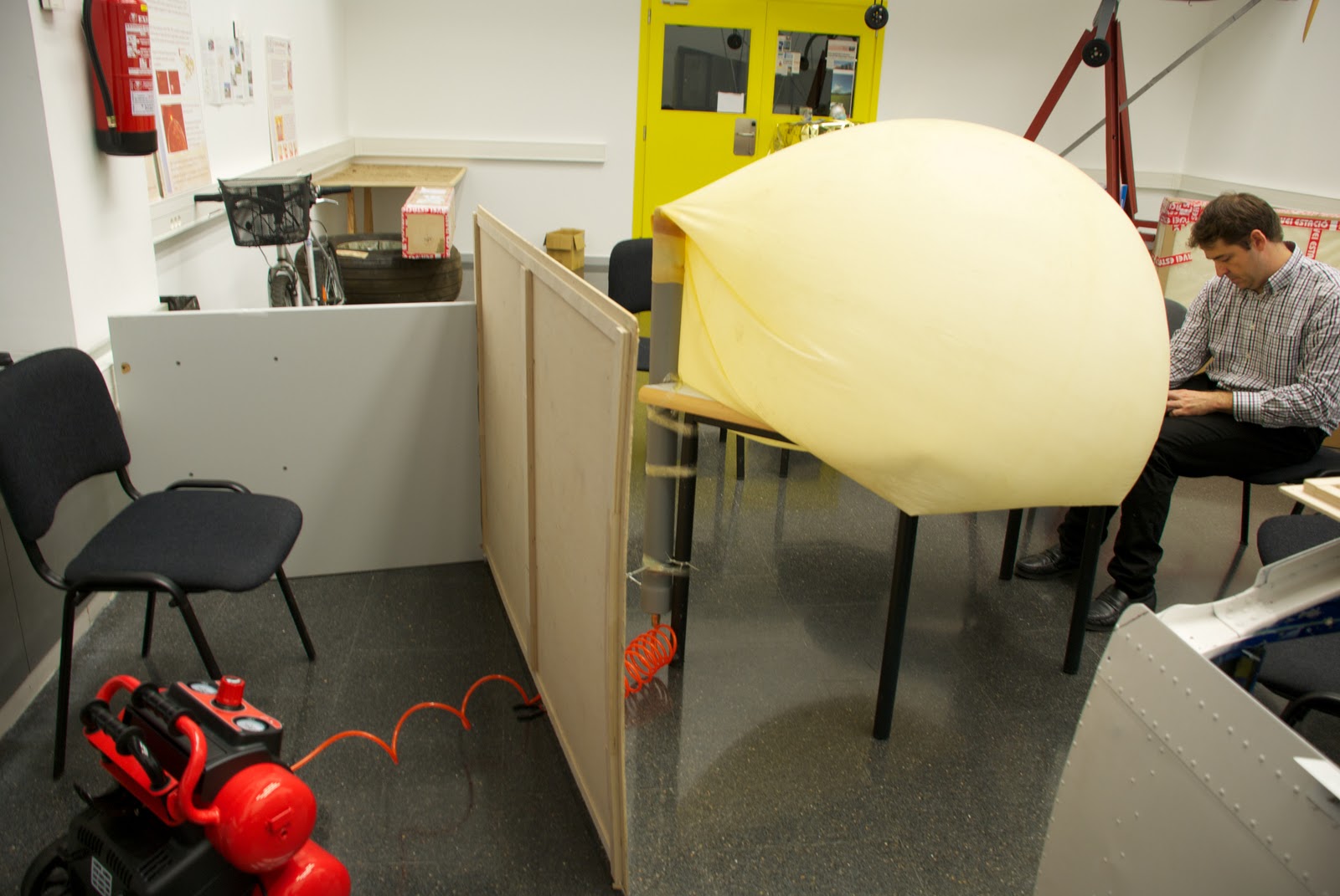
It dries in minutes and is completely seated within 3 days, in our case it isn't necessary to wait so long.Once dry the adhesive, is necessary to put the cap on the other end of the tube with a silicone adhesive and let allowed to dry several hours (Picture #3, 4 & 5). Once dry, proceed to place the tube upright because doing so will more faithfully reproduce the process that would continue the balloon-PVCpipe system, if it was "released", as attached to a table by heat (either prune used duct tape, etc) and a clamp. (Picture #6)
Finally we add the connectors (PVC pipe) and female from the compressor.Place a wood protection (picture #7 & 8) to protect us in case we get to have high pressures in the balloon-PVCpipe system and can cause some type of release (eg PVC cap)

Playing Test #2: We started to use compressed air and see how the balloon begins to swell. when this begins to have a considerable volume, tables and chairs are put under in order to hold up the tube as if the embers rise (this is, again, to play the position would have the balloon with PVC pipe), after a good while introducing air, desist. We conclude that our compressor is not powerful enough to give the pressure-flow we need. We then proceed to see the behavior of the inflated balloon. (Picture #9, 10 & 11)


Test # 2 Result: FAILED test pressure due to the compressor. As far as the behavioral test we referred to some conclusions, the first is that it did not put the pipe with the noozle of the balloon and was a bit crooked (Picture #12), this is not a serious incident as probably only give us an inclination to the PVC pipe, but if this is likely to stay very crooked that compromised the properties of the balloon (that can exploit at an inappropriate height). The second conclusion we draw is that the nozzle PVC balloon air is not lost and with a simple clamp (only for extreme caution) this would be perfectly capable of supporting the weight of the PVC pipe over the payload.


Castellano
El martes decidimos (Joshua y yo) hacer un test de presión y comportamiento del tubo de PVC con el globo de látex "acoplado". Este se llamará test #1 y constará de lo siguiente:

Test #1: Comprobar que el tubo de PVC es capaz de soportar las altas presiones a las que será sometido a medida que ascienda y ver el comportamiento del globo al hincharse (esto es ver si se aguanta sujeto, si pierde aire por la unión, etc.).

Preparación Test #1: Sellar el extremo abierto del tubo de PVC con un tapón (también de PVC), a este tapón se le acoplará un conector macho para mangueras de aire comprimido, sellado y sujetado con resina epoxy. (picture #2)
Esta se seca en cuestión de minutos y se asienta totalmente a los 3 días, en nuestro caso no será necesario esperar tanto tiempo.
Una vez seco el adhesivo se procede a poner el tapón en el otro extremo del tubo mediante un adhesivo de silicona y se deja secar varias horas (Picture #3, 4 y 5). Una vez seco se procede a colocar el tubo en posición vertical ya que de este modo podremos reproducir más fielmente el proceso que seguiría el sistema globo-tuboPVC, en el caso de que fuera "lanzado", lo acoplamos a una mesa mediante celo (bien podaría usarse cinta aislante, cinta americana, etc) y una abrazadera. (Picture #6)
Finalmente unimos los conectores macho (del tubo de PVC) y hembra procedente del compresor.
colocamos una protección de madera (picture #7 y 8) a fin de protegernos en el caso de que lleguemos a tener altas presiones en el sistema globo-tuboPVC y pueda producirse algún tipo de desprendimiento (por ejemplo del tapón de PVC)

Reproducción Test #2: Empezamos a introducir aire comprimido y vemos como el globo empieza a hincharse. cuando este empieza a tener un volumen considerable vamos poniendo mesas y sillas debajo para que se aguante encima del tubo como si este estubiera subiendo (esto es, otra vez, para reproducir la posición que tendria el globo con el tubo de PVC), al cabo de un buen rato introduciendo aire, desistimos. Llegamos a la conclusión de que nuestro compresor no es suficientemente potente para dar la presión-caudal que necesitamos. Procedemos entonces a ver el comportamiento del globo hinchado. (Picture #9, 10 y 11)

Resultado Test #2: Test de presión FALLIDO debido al compresor. Por lo que al test de comportamiento se refiere llegamos a algunas conclusiones, la primera es que no pusimos bien el tubo con la boquilla del globo y quedó un poco torcido (Picture #12), esto no es un incidente grave ya que seguramente solo nos daría una inclinación al tubo de PVC, pero si este quedara muy torcido es probable que comprometiera las propiedades del globo (pudiendo este explotar a una altura inapropiada), la segunda conclusión a la que llegamos es que por la parte de la boquilla del globo en su unión con el tubo de PVC no se pierde aire y que con una simple abrazadera (solo por extremar las precauciones), este seria perfectamente capaz de soportar el peso del tubo de PVC más su carga de pago.


Pictures (Fotos):


 Picture #1
Compressor.
Compresor.


Picture #2
PVC cap with the plug.
Tapón de PVC con el conector "macho".


Picture #3
Putting the adhesive.
Poniendo el adhesivo.

Picture #4
Putting the cap.
Poniendo el tapón.


Picture #5
Cleaning adhesive excess.
Limpiando el exceso de adhesivo.
Picture #6
Balloon-PVCpipe sistem and compression position.
Posición del sistema globo-tuboPVC con el compresor.
Picture #7
Wood protection.
Protección de madera.
Picture #8
Compressor and balloon-PVCpipe connected.
Compressor y globo-tuboPVC conectados.
Picture #9
Inflated balloon.
Globo hinchandose
 Picture #10
Picture #11
Test stopped.
Test parado.
 Picture #12
We can see that the ballon is crooked.
Podemos ver que el globo esta torcido.