Mostrando entradas con la etiqueta comportamiento. Mostrar todas las entradas

miércoles, 5 de enero de 2011

Vector control


English
As we have said many times, our short-term goal is to make a rocket capable of reaching space (minimum 100 km), but thinking long term, this rocket will not just be to reach space but also we want to control the path in order to accurately place in orbit the wiki-sats as well as we can, so Roberto is responsible for the future manufacture and test of the definitive vector control rocket. The vector control of our satellite is based on 4 small copper tubes with a very small diameter, with a valve controlled by a servo in turn controlled by a satellite that will go in the rocket, the theoretical performance is simple, our wiki-sats are fitted with accelerometers, they look at the attitude of the rocket and corrected according to a prescribed path, if necessary, by air pressure expulsion (generated by the combustion of rocket) for the tubes may change as well in all three axes (pitch , Roll and yaw). In practice it is not as simple as it is not only the production itself with the servo valves and tubes (and in itself complicated by the small scale) but also have to find the appropriate control algorithms (a followed by mathematical formulas for how much you have to open a valve or another to make a turn more or less closed or faster). What you can see in the video are the tests that have been made of the vector control system to see if the valves closed withstand the pressure and also see if the system works.


Castellano
Como ya hemos repetido numerosas veces, nuestro objetivo a corto plazo es hacer un cohete capaz de llegar al espació (mínimo 100 km), pero pensando en largo plazo, este cohete no solo tendrá que llegar al espacio sino que además querremos controlar la trayectoria de este a fin de colocar con la mayor precisión los wiki-satélites en sus óptimas órbitas, por eso Roberto es el encargado de fabricar y probar el futuro control vectorial del cohete definitivo. El control vectorial de nuestro satélite se basa en 4 pequeños tubitos de cobre de un diámetro muy pequeño, con unas válvulas controladas por unos servos a su vez controladas por uno de los satélites que irá en el cohete, el funcionamiento teórico es simple, nuestros wiki-sats estan dotados de acelerómetros, estos miran la actitud del cohete y la corrigen según una trayectoria estipulada si es necesario mediante la expusión de aire a presión (generado por la combustión del cohete) por los tubitos pudiendo cambiar así en los tres ejes (cabeceo, alabeo y guiñada). En la práctica no es tan simple pues no es solo la fabricación en si de los servos con las válvulas y los tubitos (ya de por si complicado debido a su reducida escala) sinó que también se tienen que encontrar los algoritmos de control idoneos (un seguido de formulas matemáticas para saber cuanto se tiene que abrir una válvula o otra para hacer un giro más o menos cerrado o rápido). Lo que podeis ver en el vídeo son las pruebas que se le han practicado al sistema de control vectorial para ver si las válvulas aguantan cerradas la presión y para ver también si el sistema funciona.

domingo, 12 de diciembre de 2010

Monegros launch test


English
In our plan, the first step was the validation of our Stage2 on the ground, this means, throw our stage from the ground with all the limitations we have to attest that our Stage2 will be desired. So we decided to head towards the desert of Monegros (Zaragoza) to test our stage safely. 

Test: Ground test of our stage, see the behavior, analyze the launch and see what can be improved. 

Test results: We prepared a check list, but we failed a component that is not critical, we have to weld a mass and gas welder that we had, do not work (we think due the cold), this mass function is used to make our called "payload" formed by the GPS and our board AWIP to do a tracking of the stage, this was a secondary test for as we say before, our main objective in this test is to see the behavior of the stage. This is the first test (we have many miles) and arrive to the conclusion that if I was going well but that we did not, would launch the Stage2 also. So we skip the steps related to the recording of tracking and proceed to the following, we put Roberto and me each with cameras to capture the moment (a reasonable long distance) and Joshua do all pre-launch preparations. When is about to launch, the stage reached three meters making loops and drops to ten feet from where we launched, "a disaster? Was it expected? 

Test conclusions: This test gives us a starting point, therefore, is not a disaster, says that we have much work ahead, lower weight and overall structure of payload and improve system reliability (chance is not an option)


Castellano
Dentro de nuestro plan, el primer paso era la validación de nuestra segunda etapa en tierra, esto quiere decir, lanzar nuestra etapa desde el suelo con todas las limitaciones que tenemos para dar fe de que nuestra segunda etapa hará lo deseado. Así pues nos decidimos a ir dirección al desierto de los Monegros (Zaragoza) para probar con seguridad nuestra etapa.

Test: Prueba en suelo de nuestra etapa, ver el comportamiento, analizar el lanzamiento y ver que se puede mejorar.

Resultados del test: Nos preparamos una check list, pero nos falla un componente que no es crítico, tenemos que soldar una masa y el soldador de gas que llevamos no funciona (creemos que por el frío), esta masa sirve para hacer que funcione nuestra supuesta "carga de pago" formada por el GPS y nuestra placa AWIP para poder hacer un tracking de la etapa, esto era una prueba secundaria pues como decimos antes, nuestro objetivo principal en este test es ver el comportamiento de la etapa. Esta es la primera prueba (hemos hecho muchos quilometros) y ya llegamos a la conclusion que si iba bien pero que si no iba, lanzariamos igualmente la segunda etapa. Así pues nos saltamos los pasos relacionados a la grabación del tracking y pasamos a los siguientes, nos colocamos Roberto y yo con sendas cámaras para inmortalizar el momento (a una distancia siempre prudencial) y Joshua hace todos los preparativos pre-lanzamiento. Cuando esta a punto lanza, la etapa llega a unos tres metros haciendo loopings y cae a tres metros de donde lo hemos lanzado, ¿un desastre? ¿era lo esperado?

Conclusiones del test: Este test nos da un punto de salida, por lo tanto, no es un desastre, nos dice que tenemos mucho trabajo por delante, rebajar pesos de estructura y sobretodo de carga de pago y mejorar la fiabilidad del sistema (el azar no es una opción)

martes, 30 de noviembre de 2010

Stage2 third burn


English
Following the validation of the stage2 we got to the third version of it. In this third prototype we decided to move to higher and place the savage amount of 7 grains (1 plant with its encapsulation of cardboard and its nozzle and 6 around without encapsulation or nozzle) with this configuration we reach the maximum capacity of the can. At first it wanted to put 8 grains (1 in the center and 7 around) but it was impossible to enter and so we opted for the 7-grain configuration. These 7 grains are not subject to the anothers and the can only be diposit a little resin on the bottom to support the central grain. Only the central grain is expected to igniter and the other 6 are switched to heat, pressure and fire to detach it. The can is coated with epoxy resin in order to support higher temperatures. 

Test: The test is still the same, turn on the stage and see how it reacts. 

Test result: The igniter works and lights up the stage this, but exploits a few moments of ignition by blowing up the grains that were not subject these to not be exposed to any pressure, which burned paper. 

Test conclusions: very important to hold ALL the grains so that if there is an explosion (as in our case) they do not go flying around.


Castellano
Siguiendo con la validacion de la segunda etapa llegamos a la tercera versión de la misma. En este tercer prototipo decidimos pasar a mayores y colocar la bárbara cantidad de 7 granos (1 central con su encapsulado de cartón y su tobera y 6 a su alrededor sin encapsulado ni tobera) con esta configuración llegamos a la capacidad máxima de la lata. En un principio se querian poner 8 granos (1 en el centro y 7 al rededor) pero fué imposible hacer que entraran y por eso se optó por la configuración de 7 granos. Estos 7 granos no estan sujetos entre si y la lata, solo se diposita un poquito de resina en el fondo para soportar el grano central. Solo el grano central tiene igniter y se espera que los otros 6 se enciendan con el calor, presión y fuego que desprenda este. La lata está recubierta de resina epoxy a fin de que soporte más altas temperaturas.

Test: El test sigue siendo el mismo, encender la etapa y ver como reacciona.

Resultado del test: El igniter funciona y enciende la etapa, esta, pero, explota a pocos instantes de la ignición haciendo volar por los aires los granos que no estaban sujetos, estos al no estar expuestos a presión alguna, se queman cual hoja de papel.


Conclusiones del test: muy importante sujetar TODOS los granos a fin de que si hay una explosión (como ha sido nuestro caso) estos no salgan volando por allí.

Stage2 fifth burn


English
And with this we reach the fifth prototype of the Stage2 and come full of "improvements" (If we use the slang of the Formula 1 can say that for this prototype comes new developments). If recapitulate and reminisced about the rights and wrongs of the other prototypes we have our fifth stage, it consists of an insulating coating of epoxy resin on the inside of the can so that it could withstand the high temperatures generated, in this case we use a configuration central grain surrounded by five others naked grains, in this prototype beans that go around are covered with a layer of resin with fiber, so we contain grains and further protect the can (our weak link) is due to the augment in grain volume so we could not six grains and in the last two prototypes, we have also smoothed the crust of central grain board to laces and entry though pimples. 

Test: More of the same, see the behavior of the can (and grains) in ignition. 

Test result: The igniter fails, and we have many faults, then decided to ignite "manually" via a wick. This goes on and we see a perfect "wake", the can hold the entire process. At the end we see that the nozzle is clear because the resin that hold it has been burned. 

Test conclusions: The test is a success (except that the igniter does not burn the grain), the can (remember, our weak link) hold for the first time a configuration of more than 1 grain. But here, even to amateurs, we are perfectionists and we see that the wake takes "jolts" due to the grains do not burn in unison, this certainly derive a serious departure from the stage if we would launch it. Our next step should be to think of a way to ensure that light up all at the same instant.

Castellano
Y con esta llegamos al quinto prototipo de segunda etapa y viene cargadita de "mejoras" (Si utilizamos el argot de la Formula 1 podriamos decir que para este prototipo nos llegan nuevas evoluciones). Si recapitulamos y rememoramos los errores y aciertos de los otros prototipos tenemos nuestra quinta etapa, esta consta de un recubrimiento aislante de resina epoxy por el interior de la lata para que esta soporte las altas temperaturas que se generan, en este caso utilizamos una configuración de grano central rodeado de otros cinco, en este prototipo los granos que van alrededor estan recubiertos por una capa de resina con fibra, de esta manera contenemos los granos y protegemos aún más la lata (nuestro eslabón débil) es debido a este augmento en el volumen de los granos por lo que no hemos podido seis granos como en las dos últimos prototipos, además hemos limado la corteza de cartón del grano central para poder encagar y hacer entrar bien todos los granos.

Test: Más de lo mismo, ver el comportamiento de la lata (y los granos) en ignición.

Resultado del test: El igniter falla, ya llevamos diversos fallos, entonces se decide a igniciar "manualmente" mediante una mecha. Este se enciende y vemos una perfecta "estela", la lata aguanta todo el proceso. Al final vemos que la tobera se desprende debido a que se ha quemado la resina que lo sujeta.


Conclusiones del test: El test és un éxito (salvo por que el igniter no enciende el grano), la lata (recordamos, nuestro eslabón débil) aguanta por primera vez una configuración de más de 1 grano. Pero aquí, aún que amateurs, somos perfeccionistas y vemos en el test que la estela da "bandazos" debidos a que los granos no se queman al unísono, esto derivaria seguramente en una seria desviación de la etapa si la lanzaramos. Nuestro siguiente paso deberia ser pensar en alguna manera de asegurarnos que se enciendan todos al mismo instante.

jueves, 18 de noviembre de 2010

Stage2 path simulations

English
We continue with our particular space race and now it is the turn of a key part of the project, the balloon. As we have explained our mission consist to reach space by a rocket launched from a balloon, our theory is that saving all the friction on the surface of the earth, we need smaller (and cheaper) rockets to get to space. 
We are still at the beginning of the rocket creation, so we are at our worst case, we have a heavy rocket, amateur fuel, little aerodynamic, etc. so now we can only improve. So we do some behavior simulations of our rocket launched from different altitudes. The initial altitudes are going to give the maximum altitudes for balloons can get from our distributor, you can see in Table #1. In this Table #1 you can see the type which corresponds to the weight, we can see the diameter of the neck which in our case is very important because our private launch ramp is inserted into the nozzle, we can also see the size (Bodylength), payload which is very important because exceed this charge can result in not reaching the desired altitude, the lift that makes you the balloon when it is loaded (Free Lift) and finally the maximum altitude that it can reach (Averl.Altitude). On the other side has been ignored in this table the length of the neck and the rate of climb (which is 350 m/min for all types).
Then we did a simulation with the latest prototype of rocket that have proven (this is the one used in the previous test) with a payload consisting of the GPS-AWIP explained in the entry "Tracking system". So the weights are as follows: 

Structure weight: 128.8 g 
Grains weight: 195.3 g 
Fill Weight: 50 gr 
Payload: 167.8 g 
Total: 541.9 g 

In Table #2 and Graphic #1 we can see the simulation results with the balloon types, burst altitude, Balloon diameter and the Apogee. If we analyze the results we realize that we don't reach our goal, but everything will come, now we must think about how and what to improve in order to reach our goal. Basics, reduce weight of the filling and the payload, every day we work to make the payload and a lighter structure.


Castellano
Seguimos con nuestra particular carrera hacia el espacio y ahora le llega el turno a una parte fundamental del proyecto, el globo. Como hemos explicado nuestra misión consiste en llegar al espacio con un cohete lanzado desde un globo, nuestra teoria es que ahorrandonos toda la fricción que hay en la superficie de la tierra necesitaremos cohetes más pequeños (y baratos) para llegar al espacio.
Aun estamos en los inicios de la creación del cohete, por lo tanto estamos en nuestro peor caso, nos encontramos con un cohete pesado, de combustible amateur, poco aerodinamico, etc. por lo tanto ahora solo podemos mejorar, así pues vamos a hacer unas simulaciónes del comportamiento de nuestro cohete lanzado desde diferentes altitudes. Las altitudes iniciales las van a dar las altitudes máximas a las que pueden llegar los globos de nuestro distribuidor, estos los podeis ver en la Table #1. En esta Table #1 podeis apreciar el tipo (type) que se corresponde con el peso (weight), podemos ver el diametro de la boquilla (Neckdiam.) que en nuestro caso es muy importante pues nuesta lanzadera va insertada dentro de esta boquilla, también podemos ver la envergadura (Bodylength), la carga de pago o carga útil (Payload) muy importante pues sobrepasar esta carga puede tener como consecuéncia no llegar a la altitud deseada, el empuje que te hace el globo cuando esta cargado (Free Lift) y por último la altitud máxima a a que puede llegar (Averl.Altitude). Por otro lado se ha obviado de esta tabla la longitud de la boquilla y la velocidad de ascenso (que es de 350 m/min para todos los tipos).

Entonces hemos hecho una simulación con el último prototipo de cohete que hemos provado (este es el que se utilizó en la anterior prueba) con una carga de pago consistente en el sistema GPS-AWIP explicado en la entrada "Tracking system". Así pues los pesos quedan de la siguiente manera:

Peso estructura: 128.8 gr
Peso granos: 195.3 gr
Peso Relleno: 50 gr
Payload: 167.8 gr
Total: 541.9 gr

En la Table #2 y Graphic #1 podemos ver los resultados de la simulación con el tipo de globo (Type), la altitud màxima del globo (burst altitude), el diametro del globo (Balloon diameter) y hasta donde llega el cohete o apogeo (Apogee). Si analizamos los resultados nos damos cuenta de que no llegamos a nuestra meta, pero todo se andará, tenemos que pensar en como y que mejorar para poder llegar a nuestro objetivo. Lo básico, reducir peso del relleno y el payload, dia a dia trabajamos para hacer ese payload y una estructura más ligera.

Links:
http://www.meteorologyshop.eu/Radiosonding_balloons/ENG_276_EUR_38_0__.html


Table #1:
Overview of deliverable pilot balloons
Type Weight(g)
Neckdiam. (cm)
Bodylength
(cm)
Payload
(g)
Free Lift
(g)

Averl.Altiude (km)
100
1,4±0,3
55 200 480
18,5
200
3,2±0,4
75 300 1150
21,0
300 300±15
3,2±0,4
95 650 950
24,0
500 500±25
3,2±0,4
130 1150 1250
26,5
600 600±27
3,2±0,4
145 1150 1300
28,5
700 700±28
3,2±0,4
160 1150 1300
29,5
800 800±30
3,2±0,4
170 1150 1350
30,5
1000 1000±31
3,2±0,4
180 1150 1400
32,5
1200 1200± 45
3,2±0,4
200 1150 1400
33,5
1500 1500±50
3,2±0,4
220 1150 1500
35,0
2000 2000±80
5,0±0,4
250 1150 1550
37,0
3000 3000±110
5,0±0,4
295 1150 1600
39,0


Table #2:
Type BURST Altitude Balloon diameter Apogee
100gr 18,5 km 0,55 m 24,7 km
200gr 21,0 km 0,75 m 29,0 km
300gr 24,0 km 0,95 m 35,0 km
500gr 26,5 km 1,30 m 40,8 km
600gr 28,5 km 1,45 m 45,8 km
700gr 29,5 km 1,60 m 48,5 km
800gr 30,5 km 1,70 m 51,1 km
1000gr 32,5 km 1,80 m 56,3 km
1200gr 33,5 km 2,00 m 58,8 km
1500gr 35,0 km 2,20 m 62,3 km
2000gr 37,0 km 2,50 m 66,8 km
3000gr 39,0 km 2,95 m 70,8 km

Table #3:
Click on the picture to maximize.
Haz click en las foto para maximizar.


Pictures (Fotos):
Click on the pictures to maximize.
Haz click en las fotos para maximizar.

Picture #1

Picture #2


Graphic #1:

Blue line (Stage2): Behind the points: baloon type; Stage2 apogee. Al lado de los puntos: tipo de globo, apogeo de la Stage2
 Red line (balloon): Burst altitude; altura de explosión

 Graphic #2, #3 & #4:


miércoles, 17 de noviembre de 2010

Stage2 fourth burn


English
We keep testing the Stage2 and before explain and analyze the results of the fourth test we will review progress and findings of the other three tests. 
In the first test we tested the can with a single-engine jet amateur, the results that we see are that the can is heated and deformed through the nozzle thrust, therefore see that the nozzle works. 
In the second test we decided to put 4 engines, the result is that our can exploit a little over a second after being fired, we make a mistake by not covering the inside of the can with more resin to withstand the high temperatures that are reached within the can.In the third test we decided to put 7 grains, but this time only put one with its amateur nozzle and the other six are placed around without the wrapper, with this we want to get more burn time, the result is that the bulkhead is released and the nozzle flies shedding all the content.

In this fourth test we put  7 grain one wrap with cardboard and the other six covered with a layer of resin, to the grain that we don't take off the bundle it will be a bit depress so you can enter the other 6 grains, once put these inside is filled with resin.

Test: As in other cases, the objective of this test is to burn the Stage2 and watch their behavior in order to achieve an stable and reliable stage to reach space.
Test result: we ignite the stage (with our famous FIREBOX), the stage burns and about 3 seconds after it we see how (in milliseconds) there is a leak in the structure resulting in an explosion, then you can see resin burns inside. The nozzle holds perfectly and  is only after a while burning the resin that holds, that this come off, then we also see that the blast open the can in a very curious way then the can cut is nearly perfect as we can see in the video images being opened only by the sides. The bulkhead holds.

Test conclusions: The resin well spread within the can gives greater resistance to pressure and temperature to seeing increased almost twice as long as you hold the nozzle before giving up. The nozzle despite being inaluminum, once cleaned, it looks like new, important to protect the inside with epoxy resin.


Castellano
Seguimos probando la segunda etapa y antes de explicar y analizar los resultados de esta cuarta prueba vamos a analizar los avances y descubrimientos de las otras tres pruebas.
En el primer test probamos la tobera con un solo motor amateur, el resultado es que vemos que la lata se nos calienta y deforma debido o gracias al empuje que da la tobera, por lo tanto vemos que la tobera funciona.
En el segundo test decidimos poner 4 motores, el resultado es que nuestra lata explota al segundo y poco, cometemos un error al no forrar la parte interior de la lata con resina para que resista más las altas temperaturas a las que se llega dentro de la lata.
En el tercer test decidimos poner 7 granos, pero esta vez solo ponemos uno con su tobera amateur y los otros seis se ponen alrededor sin el envoltorio, con esto se quiere conseguir más tiempo de combustión, el resultado es que el mamparo se suelta y la tobera sale volando desprendiéndose todo.

En este cuarto test volvemos a poner 7 granos uno con su envoltorio de carton y los otros seis forrados de una capa de resina, al grano que no se le quita el envoltorio se le rebaja este un poco para que se puedan introducir los otros 6, una vez puestos estos dentro se llena de resina.

Test: Como en los otros casos, el objetivo de este test es el de quemar la segunda etapa y ver su comportamiento a fin de conseguir una etapa estable y fiable para poder llegar al espacio.

Resultado del test: Encendemos la etapa (con nuestra famosa FIREBOX), la etapa se enciende y alrededor de 3 segundos después se ve como (en milésimas de segundo) hay una fuga en la estructura que da como resultado una explosión, luego se puede ver como se quema la resina del interior. La tobera aguanta perfectamente y es solo al cabo de un rato quemando la resina que la sujeta que esta se desprende, luego también vemos que la explosión abre la lata de una manera muy curiosa pues el corte de la lata es casi perfecto como podemos ver en las imagenes del vídeo abriéndose solo por los laterales. El mamparo aguanta.

Conclusiones del test: La resina bien esparcida dentro de la lata nos da una resistencia superior a la presión y temperatura viendo aumentado casi en el doble el tiempo que aguanta la tobera antes de ceder. La tobera a pesar de ser de aluminio, una vez limpiada, se ve como nueva, importante proteger la parte interior con resina epoxy.

martes, 9 de noviembre de 2010

Destructive can & noozle test (Stage2 second burn)


English
On our way to the validation of components arises we need to put the components to the limit, these components are the famous soda can (with testing and pressure testing) and the nozzle, in the last test results were quite satisfactory in this test we want to limit our cans and nozzles. 

Test: Put the can and the nozzle to the limit, that we will do putting 4 other amateur engines into the can, then analyze the results. 

Test result: The igniters flaunt their reliability and ignite, watching the video in slow motion we can see that is not immediately gone on the 4 but few go on before others (miliseconds). The combustion of these engines takes less than 3 seconds. Before the first combustion second the can burst, we see a clean cut. Before the explosion is possible to see the nozzle to its function has not been calculated yet the thrust. 

Conclusions: We have several theories about the cause of the blowout, one can be that much that can swell in contact with the clamp that can support this cutting off the can, another may be that in the can we put a cut can to strengthen and maintain engines together, so this can may have extensive playing outside and cutting the can (it was a little bad cut). More theories are that can not resist the pressure that a flaw in the can give in under pressure. 
On the other hand we realize that we can not put these engines as it is in the can since they already have their nozzle and when ignited are like torches and we see that in the little time that they are lit before the can burst, it make holes in the interior of the aluminum nozzle, our next goal is to turn the motor fuel only amateur. 
Let us not forget the bulkhead, this will hold.


Castellano
En nuestro camino a la validación de componentes nos urge la necesidad de poner al límite a los componentes, estos componentes son la famosa lata de refresco (puesta a prueba ya con pruebas de presión) y la tobera, en el pasado test los resultados fueron bastante satisfactorios, en este test queremos poner al límite a nuestra lata y tobera.

Test: Poner al límite a la lata y la tobera, esto lo vamos a hacer poniendo 4 motores amateur dentro, después analizar los resultados.

Resultado del test: Los igniters hacen gala de su fiabilidad y se encienden, viendo el vídeo a cámara lenta se ve que no se han encendido al instante los 4 sino que unos se encienden antes que otros (por milésimas). La combustión de estos motores tarda poco menos de 3 segundos. Antes del segundo de combustión nuestra lata revienta, se ve un corte limpio. Antes de la explosión es posible ver a la tobera hacer su función, no se ha calculado aún el empuje.

Conclusiones: Tenemos diversas teorías sobre la causa del reventón, una puede ser que la lata se hinchara tanto que al contacto con la abrazadera que la soporta esta cortara la lata, otra puede ser que dentro de la lata pusimos una lata recortada para reforzar y mantener juntos los motores, así que esta lata puede haberse dilatado tocando la lata exterior y cortándola (ya que estaba un poco mal cortada). Más teorías, que la lata no aguante la presión, que una imperfección en la lata cediera por la presión.
Por otra parte nos damos cuenta que no podemos poner estos motores tal cual dentro de la lata ya que estos ya tienen su tobera y cuando se encienden son como sopletes y vemos que en el poquisimo tiempo que estos estan encendidos antes de que la lata reviente, hacen agujeros en la parte interior de la tobera de aluminio, nuestro próximo objetivo es encender solo el combustible del motor amateur.
No nos olvidamos del mamparo, este aguanta perfectamente.


Pictures (Fotos):

 Picture #1
Picture #2
Picture #3
Picture #4
Picture #5
Picture #6
 Picture #7
Picture #8
Picture #9

Picture #10
Picture #11
Picture #12

domingo, 10 de octubre de 2010

Launch plan (without dates)

English
Ground certification
  • Launch the rochet on the ground.
Balloon - Launch ramp certification
  • Launch the balloon with the launch ramp to see the height at which they reach (this has to be recoverable).
  • Test comunications (tracking).
Launch test
  • Launch ramp certification.


Castellano
Certificación en tierra
  • Lanzar el cohete en tierra.
Certificación del globo - rampa de lanzamiento
  • Lanzar el globo con la rampa de lanzamiento para ver a que altura llega (ha de ser recuperable).
  • Probar las comunicaciones (seguimiento).    
Prueba de lanzamiento 
  • Certificación de la lanzadera.

Test #1: Preassure & behavior test

English
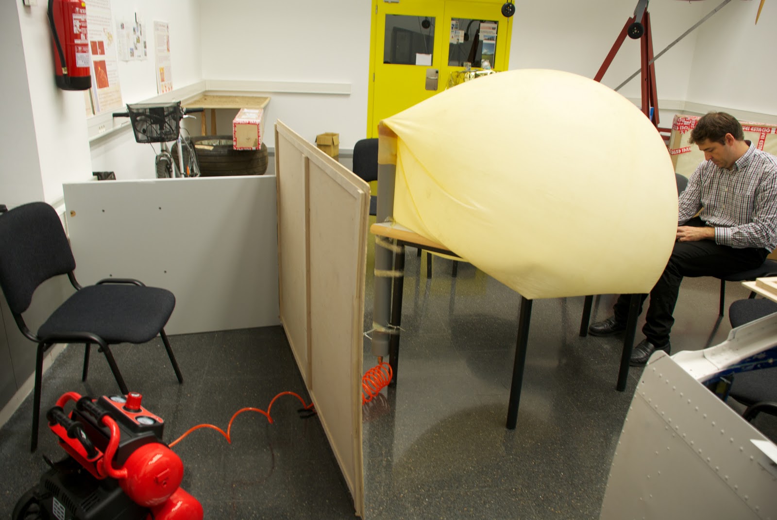
On tuesday we (Joshua & me) decide to do a preasure test and behavio of PVC pipe with attached latex balloon. It will be called test #1and consist of the following:

Test #1: Make sure the PVC pipe can withstand the high pressures that will be submitted as you move up and see the behavior of the balloon to swell (see if it holds subject, if the union loses air, etc. ).

Preparation Test #1: Seal the open end of PVC pipe with a stopper (also PVC), this cap is coupled to a plug connector for compressed air hoses, sealed and secured with epoxy resin. (picture #2)
It dries in minutes and is completely seated within 3 days, in our case it isn't necessary to wait so long.Once dry the adhesive, is necessary to put the cap on the other end of the tube with a silicone adhesive and let allowed to dry several hours (Picture #3, 4 & 5). Once dry, proceed to place the tube upright because doing so will more faithfully reproduce the process that would continue the balloon-PVCpipe system, if it was "released", as attached to a table by heat (either prune used duct tape, etc) and a clamp. (Picture #6)
Finally we add the connectors (PVC pipe) and female from the compressor.Place a wood protection (picture #7 & 8) to protect us in case we get to have high pressures in the balloon-PVCpipe system and can cause some type of release (eg PVC cap)

Playing Test #2: We started to use compressed air and see how the balloon begins to swell. when this begins to have a considerable volume, tables and chairs are put under in order to hold up the tube as if the embers rise (this is, again, to play the position would have the balloon with PVC pipe), after a good while introducing air, desist. We conclude that our compressor is not powerful enough to give the pressure-flow we need. We then proceed to see the behavior of the inflated balloon. (Picture #9, 10 & 11)


Test # 2 Result: FAILED test pressure due to the compressor. As far as the behavioral test we referred to some conclusions, the first is that it did not put the pipe with the noozle of the balloon and was a bit crooked (Picture #12), this is not a serious incident as probably only give us an inclination to the PVC pipe, but if this is likely to stay very crooked that compromised the properties of the balloon (that can exploit at an inappropriate height). The second conclusion we draw is that the nozzle PVC balloon air is not lost and with a simple clamp (only for extreme caution) this would be perfectly capable of supporting the weight of the PVC pipe over the payload.


Castellano
El martes decidimos (Joshua y yo) hacer un test de presión y comportamiento del tubo de PVC con el globo de látex "acoplado". Este se llamará test #1 y constará de lo siguiente:

Test #1: Comprobar que el tubo de PVC es capaz de soportar las altas presiones a las que será sometido a medida que ascienda y ver el comportamiento del globo al hincharse (esto es ver si se aguanta sujeto, si pierde aire por la unión, etc.).

Preparación Test #1: Sellar el extremo abierto del tubo de PVC con un tapón (también de PVC), a este tapón se le acoplará un conector macho para mangueras de aire comprimido, sellado y sujetado con resina epoxy. (picture #2)
Esta se seca en cuestión de minutos y se asienta totalmente a los 3 días, en nuestro caso no será necesario esperar tanto tiempo.
Una vez seco el adhesivo se procede a poner el tapón en el otro extremo del tubo mediante un adhesivo de silicona y se deja secar varias horas (Picture #3, 4 y 5). Una vez seco se procede a colocar el tubo en posición vertical ya que de este modo podremos reproducir más fielmente el proceso que seguiría el sistema globo-tuboPVC, en el caso de que fuera "lanzado", lo acoplamos a una mesa mediante celo (bien podaría usarse cinta aislante, cinta americana, etc) y una abrazadera. (Picture #6)
Finalmente unimos los conectores macho (del tubo de PVC) y hembra procedente del compresor.
colocamos una protección de madera (picture #7 y 8) a fin de protegernos en el caso de que lleguemos a tener altas presiones en el sistema globo-tuboPVC y pueda producirse algún tipo de desprendimiento (por ejemplo del tapón de PVC)

Reproducción Test #2: Empezamos a introducir aire comprimido y vemos como el globo empieza a hincharse. cuando este empieza a tener un volumen considerable vamos poniendo mesas y sillas debajo para que se aguante encima del tubo como si este estubiera subiendo (esto es, otra vez, para reproducir la posición que tendria el globo con el tubo de PVC), al cabo de un buen rato introduciendo aire, desistimos. Llegamos a la conclusión de que nuestro compresor no es suficientemente potente para dar la presión-caudal que necesitamos. Procedemos entonces a ver el comportamiento del globo hinchado. (Picture #9, 10 y 11)

Resultado Test #2: Test de presión FALLIDO debido al compresor. Por lo que al test de comportamiento se refiere llegamos a algunas conclusiones, la primera es que no pusimos bien el tubo con la boquilla del globo y quedó un poco torcido (Picture #12), esto no es un incidente grave ya que seguramente solo nos daría una inclinación al tubo de PVC, pero si este quedara muy torcido es probable que comprometiera las propiedades del globo (pudiendo este explotar a una altura inapropiada), la segunda conclusión a la que llegamos es que por la parte de la boquilla del globo en su unión con el tubo de PVC no se pierde aire y que con una simple abrazadera (solo por extremar las precauciones), este seria perfectamente capaz de soportar el peso del tubo de PVC más su carga de pago.


Pictures (Fotos):


 Picture #1
Compressor.
Compresor.


Picture #2
PVC cap with the plug.
Tapón de PVC con el conector "macho".


Picture #3
Putting the adhesive.
Poniendo el adhesivo.

Picture #4
Putting the cap.
Poniendo el tapón.


Picture #5
Cleaning adhesive excess.
Limpiando el exceso de adhesivo.
Picture #6
Balloon-PVCpipe sistem and compression position.
Posición del sistema globo-tuboPVC con el compresor.
Picture #7
Wood protection.
Protección de madera.
Picture #8
Compressor and balloon-PVCpipe connected.
Compressor y globo-tuboPVC conectados.
Picture #9
Inflated balloon.
Globo hinchandose
 Picture #10
Picture #11
Test stopped.
Test parado.
 Picture #12
We can see that the ballon is crooked.
Podemos ver que el globo esta torcido.