Mostrando entradas con la etiqueta design. Mostrar todas las entradas

lunes, 3 de enero de 2011

Launch campaign, first launch

English
In our wiki-space campaign we have decided the first launch date, this is the next January 28th. For this launch the following objectives:

    1. Launch a stratospheric balloon with our launch ramp and the system arrives at least 30 km.
    2. At 30 km high, launch a rocket stage with a monitoring system.
    3. At 2 km to open a parachute.
    4. See the results, analyze and report.

Then you can see the code that we will introduce the AWIP to the igniter is turned on at 30 km and the parachute at 2 km. This has been done by Juan Martínez and Joshua Tristancho and reviewed by Victor Kravchenko.


Castellano
En nuestra wiki-campaña espacial nos hemos propuesto la primera fecha de lanzamiento, esta es el 28 de enero. Para este lanzamiento los objetivos son los siguientes:
  1. Lanzar nuestro globo estratosferico con nuestra rampa le lanzamiento y que llegue a un mínimo de 30 km.
  2. A 30 km lanzar la etapa del cohete con un sistema de seguimiento.
  3. A 2 km que se abra un paracaídas.
  4. Ver los resultados, analizarlos y reportarlos.
Seguidamente podes ver el código que le vamos a introducir a la AWIP para que que el igniter se encienda a 30 km y el paracaídas a 2 km. Este ha sido hecho por Juan Martínez y Joshua Tristancho y revisado por Victor Kravchenko.


Code (codigo):


#include <Wire.h>
#include <SoftwareSerial.h>
#include <EEPROM.h>
#include <math.h>
#define IGNITION_ALTITUDE 30000 // Above this altitude in meters the igniter is activated
#define PARACHUTE_ALTITUDE 2000 // Below this altitude in meters the parachute is deployed
#define SAFETY_ALTITUDE 3000 // Safety altitude above wich the parachute can be deployed
#define APOGEE_ADDR 0 // Apogee EEPROM Address
#define IGNITION_PIN 12 // Ouput pin number to activate the igniter 5V
#define PARACHUTE_PIN 10 // Ouput pin number to activate the parachute 5V
#define GPSRX_PIN 11 // Input pin for GPS Rx serial port
#define GPSTX_PIN 13 // Output pin for GPS Tx serial port
//#include "itg3200.h" // GYRO ITG-3200
#define GyroID B1101001
//Register 22 - FS_SEL, DLPF_CFG
#define R22 0x16
#define R22INIT B00011011
//Register 62 - Power Management
#define R62 0x3e
#define R62INIT B00000001
//Registers 27 to 34 - Sensor Registers
#define TempH 0x1b
#define TempL 0x1c
#define GyroXH 0x1d
#define GyroXL 0x1e
#define GyroYH 0x1f
#define GyroYL 0x20
#define GyroZH 0x21
#define GyroZL 0x22
//#include "lis331hh.h" Accelerometer LIS331HH
#define AccID 0x18
//Register CTRL_REG0 - Power management and conf
#define RCTR0 0x20
#define RCTR0INIT B00100111
//Sensor Registers
#define AccXH 0x29
#define AccXL 0x28
#define AccYH 0x2B
#define AccYL 0x2A
#define AccZH 0x2D
#define AccZL 0x2C
#define AccStat 0x27
void i2cSetRegister(int device, int address, int value)
{
  Wire.beginTransmission(device);
  Wire.send(address);
  Wire.send(value);
  Wire.endTransmission();
}
byte i2cGetRegister(int device, int address)
{
  Wire.beginTransmission(device);
  Wire.send(address);
  Wire.endTransmission();
  Wire.requestFrom(device, 1);
  if(Wire.available())
  return Wire.receive();
  return B00000000;
}
int i2cGetValue(int device, int addressH, int addressL)
{
  return i2cGetRegister(device, addressH) * 256 + i2cGetRegister(device, addressL);
}
// Globals
SoftwareSerial GPS = SoftwareSerial(GPSRX_PIN,GPSTX_PIN);
int addr;
int val; // Last byte read from GPS
float alt; // Last altitude read from GPS
float apogee; // Highest altitude read from GPS. This variable is mirrored in EEPROM.
byte k[]={0,0,0,0,0,0,0,0,0,0,0,0,0}; // Read buffer for GPS input
float EEPROMGetFloat(int addr)
{
  float num;
  ((byte*)&num)[0]=EEPROM.read(addr++);
  ((byte*)&num)[1]=EEPROM.read(addr++);
  ((byte*)&num)[2]=EEPROM.read(addr++);
  ((byte*)&num)[3]=EEPROM.read(addr++);
  return num;
}
void EEPROMSetFloat(int addr, float num)
{
  EEPROM.write(addr++,((byte*)&num)[0]);
  EEPROM.write(addr++,((byte*)&num)[1]);
  EEPROM.write(addr++,((byte*)&num)[2]);
  EEPROM.write(addr++,((byte*)&num)[3]);
}
byte Next()
{
  // BYTE, BIN, OCT, HEX, 1 = number of decimals
  val=byte(GPS.read());
  Serial.print(val,BYTE); // For debbuging purpose only
  return val;
}
int ReadParam(byte chr=',')
{
  int i=0;
  while(true)
    if(i>=sizeof(k))
      return -1; // Buffer overrun
    else if((k[i]=Next())==chr)
      return i; // Read 'i' bytes
    else
      i++;
}
void setup ()
{
  pinMode(IGNITION_PIN,OUTPUT);
  digitalWrite(IGNITION_PIN,LOW);
  pinMode(PARACHUTE_PIN,OUTPUT);
  digitalWrite(PARACHUTE_PIN,LOW);
  GPS.begin(4800);
  Serial.begin(4800);
 
  // EEPROM dumping
  /*
  for(addr=0;addr<512;addr++)
  {
    if (!(addr%16)){Serial.println();Serial.print(addr/1000.0f,3);Serial.print(": ");}
    Serial.print(EEPROM.read(addr)/1000.0f,3);Serial.print(" ");
    //EEPROM.write(addr,0); // WARNING: This line will erase all the EEPROM memory
  }
  Serial.println();
  */
 
  addr=0;
  val=0;
  alt=0;
  apogee=EEPROMGetFloat(APOGEE_ADDR);
  Wire.begin();
  // Hyperterminal at 57600 and Arduino at 115200 bauds
  //Serial.begin(115200);
  // Accelerometer LIS331HH setup
  i2cSetRegister(AccID, RCTR0, RCTR0INIT);
  // Gyro ITG-3200 setup
  i2cSetRegister(GyroID, R62, R62INIT);
  i2cSetRegister(GyroID, R22, R22INIT);
  // Hardware-on-the-loop config
  //i=0;
}
void loop()
{
  int i;
  if(Next()=='$')if(Next()=='G')if(Next()=='P')if(Next()=='G')if(Next()=='G')if(Next()=='A')if(Next()==',')
  {
    if(ReadParam()>=0)      // Time in UTC of position
    if(ReadParam()>=0)      // Latitude of position
    if(ReadParam()>=0)      // Latitude N or S
    if(ReadParam()>=0)      // Longitude of position
    if(ReadParam()>=0)      // Longitude E or W
    if(ReadParam()>=0)      // GPS quality                            (0=fix not available, 1=Non-differential GPS fix available, 2=Differential GPS (WAAS) fix available, 6=Estimated)
    if(ReadParam()>=0)      // Number of satellites                   (00 to 12)
    if(ReadParam()>=0)      // Horizontal dilution of precision       (0.5 to 99.9)
    if(ReadParam()>0)       // Antenna altitude above mean sea level  (-9999.9 to 99999.9)
    {
      alt=atof((char*)&k[0]);
      if(ReadParam()>=0)    // Units of antenna altitude, meters      M
      if(ReadParam()>=0)    // Height of geoid above ellipsoid        (-999.9 to 9999.9)
      if(ReadParam()>=0)    // Units of geoid height, meters          M
      if(ReadParam()>=0)    // Age of differential GPS data, seconds  Null
      if(ReadParam('*')>=0) // Differential reference station ID      Null
      if(ReadParam(10)>0)   // Checksum                               *HH
      {
        if(alt>apogee)
        {
          apogee=alt;
          EEPROMSetFloat(APOGEE_ADDR,alt);
        }
        if(alt>IGNITION_ALTITUDE)digitalWrite(IGNITION_PIN,HIGH);
        if(alt<PARACHUTE_ALTITUDE)if(apogee>SAFETY_ALTITUDE)digitalWrite(PARACHUTE_PIN,HIGH);
      }
    }
  }
}

martes, 30 de noviembre de 2010

Stage2 third burn


English
Following the validation of the stage2 we got to the third version of it. In this third prototype we decided to move to higher and place the savage amount of 7 grains (1 plant with its encapsulation of cardboard and its nozzle and 6 around without encapsulation or nozzle) with this configuration we reach the maximum capacity of the can. At first it wanted to put 8 grains (1 in the center and 7 around) but it was impossible to enter and so we opted for the 7-grain configuration. These 7 grains are not subject to the anothers and the can only be diposit a little resin on the bottom to support the central grain. Only the central grain is expected to igniter and the other 6 are switched to heat, pressure and fire to detach it. The can is coated with epoxy resin in order to support higher temperatures. 

Test: The test is still the same, turn on the stage and see how it reacts. 

Test result: The igniter works and lights up the stage this, but exploits a few moments of ignition by blowing up the grains that were not subject these to not be exposed to any pressure, which burned paper. 

Test conclusions: very important to hold ALL the grains so that if there is an explosion (as in our case) they do not go flying around.


Castellano
Siguiendo con la validacion de la segunda etapa llegamos a la tercera versión de la misma. En este tercer prototipo decidimos pasar a mayores y colocar la bárbara cantidad de 7 granos (1 central con su encapsulado de cartón y su tobera y 6 a su alrededor sin encapsulado ni tobera) con esta configuración llegamos a la capacidad máxima de la lata. En un principio se querian poner 8 granos (1 en el centro y 7 al rededor) pero fué imposible hacer que entraran y por eso se optó por la configuración de 7 granos. Estos 7 granos no estan sujetos entre si y la lata, solo se diposita un poquito de resina en el fondo para soportar el grano central. Solo el grano central tiene igniter y se espera que los otros 6 se enciendan con el calor, presión y fuego que desprenda este. La lata está recubierta de resina epoxy a fin de que soporte más altas temperaturas.

Test: El test sigue siendo el mismo, encender la etapa y ver como reacciona.

Resultado del test: El igniter funciona y enciende la etapa, esta, pero, explota a pocos instantes de la ignición haciendo volar por los aires los granos que no estaban sujetos, estos al no estar expuestos a presión alguna, se queman cual hoja de papel.


Conclusiones del test: muy importante sujetar TODOS los granos a fin de que si hay una explosión (como ha sido nuestro caso) estos no salgan volando por allí.

Stage2 fifth burn


English
And with this we reach the fifth prototype of the Stage2 and come full of "improvements" (If we use the slang of the Formula 1 can say that for this prototype comes new developments). If recapitulate and reminisced about the rights and wrongs of the other prototypes we have our fifth stage, it consists of an insulating coating of epoxy resin on the inside of the can so that it could withstand the high temperatures generated, in this case we use a configuration central grain surrounded by five others naked grains, in this prototype beans that go around are covered with a layer of resin with fiber, so we contain grains and further protect the can (our weak link) is due to the augment in grain volume so we could not six grains and in the last two prototypes, we have also smoothed the crust of central grain board to laces and entry though pimples. 

Test: More of the same, see the behavior of the can (and grains) in ignition. 

Test result: The igniter fails, and we have many faults, then decided to ignite "manually" via a wick. This goes on and we see a perfect "wake", the can hold the entire process. At the end we see that the nozzle is clear because the resin that hold it has been burned. 

Test conclusions: The test is a success (except that the igniter does not burn the grain), the can (remember, our weak link) hold for the first time a configuration of more than 1 grain. But here, even to amateurs, we are perfectionists and we see that the wake takes "jolts" due to the grains do not burn in unison, this certainly derive a serious departure from the stage if we would launch it. Our next step should be to think of a way to ensure that light up all at the same instant.

Castellano
Y con esta llegamos al quinto prototipo de segunda etapa y viene cargadita de "mejoras" (Si utilizamos el argot de la Formula 1 podriamos decir que para este prototipo nos llegan nuevas evoluciones). Si recapitulamos y rememoramos los errores y aciertos de los otros prototipos tenemos nuestra quinta etapa, esta consta de un recubrimiento aislante de resina epoxy por el interior de la lata para que esta soporte las altas temperaturas que se generan, en este caso utilizamos una configuración de grano central rodeado de otros cinco, en este prototipo los granos que van alrededor estan recubiertos por una capa de resina con fibra, de esta manera contenemos los granos y protegemos aún más la lata (nuestro eslabón débil) es debido a este augmento en el volumen de los granos por lo que no hemos podido seis granos como en las dos últimos prototipos, además hemos limado la corteza de cartón del grano central para poder encagar y hacer entrar bien todos los granos.

Test: Más de lo mismo, ver el comportamiento de la lata (y los granos) en ignición.

Resultado del test: El igniter falla, ya llevamos diversos fallos, entonces se decide a igniciar "manualmente" mediante una mecha. Este se enciende y vemos una perfecta "estela", la lata aguanta todo el proceso. Al final vemos que la tobera se desprende debido a que se ha quemado la resina que lo sujeta.


Conclusiones del test: El test és un éxito (salvo por que el igniter no enciende el grano), la lata (recordamos, nuestro eslabón débil) aguanta por primera vez una configuración de más de 1 grano. Pero aquí, aún que amateurs, somos perfeccionistas y vemos en el test que la estela da "bandazos" debidos a que los granos no se queman al unísono, esto derivaria seguramente en una seria desviación de la etapa si la lanzaramos. Nuestro siguiente paso deberia ser pensar en alguna manera de asegurarnos que se enciendan todos al mismo instante.

lunes, 15 de noviembre de 2010

Tracking system

English
 We want to take a step in our project and we met the tracking, we want to know the path that our rocket does. In another post we talk about APRS, we don't discard it yet, but we will decant to a GPS + Arduino system, the problem of this system is that we need to recover the platform to treat the data, we don't have this problem with the APRS as we receive the coordinates via radio.

GPS installation and configuration: 
We put a DB-9 female connector to the GPS, we feed it with 5 volts and connect it directly to the computer and we look at the results in the arduino's hyperterminal (speed: 4800 baud).

We can see the results in the annex #1.


The 4 sentence by default that give us the GPS are repeated periodically, we can know the meaning of each frame in the GPS specifications that you can find in the link of the Annex #2 (the GPS does not converge since we are in the lab).

Condition the GPS signal with TTL level converter. Image only use the settings to low because we only want to receive data from GPS, doeth he Transmission cable does not use GPS. 

We use a board made by us based on ATmega (Arduino), this was design  for the WikiSat project and his name is AWIP. 

We went outside with a laptop and switch on the board with the GPS, this converges almost immediately and with startling accuracy. 

As we mentioned at the beginning, the system we have chosen have not wireless transmission and therefore will have to save the data that GPS provide us. And the way this data will be stored in an EEPROM (Programmable ROM) for subsequent extraction and treatment. 

And to end we made up a safe system of ignition, it is a remote control that we call "FIREBOX". It consists of a 9 volt battery with internal circuitry and its most important function is to prevent accidentally rocket launched. First you have to turn on, some LED's warn us that the rocket is armed and the other that the GPS is aligned, once we see that the GPS is aligned, we burn the arduino to below (without wasting time and memory that we have is quite low) ignite the rocket.


Castellano
Queremos dar un paso en nuestro proyecto y nos topamos con el tracking, queremos saber el recorrido que hace nuestro cohete. En otra entrada hablamos del APRS, no lo desechamos aún pero nos vamos a decantar hacia un sistema GPS + Arduino, el problema de este sistema es que necesitamos recuperar la plataforma para poder tratar los datos mientras que con el APRS recibíamos las coordenadas via radio.

Montaje y configuración del GPS:
Ponemos un conector DB-9 hembra al GPS, lo alimentamos con 5 voltios y lo conectamos directamente al ordenador y miramos los resultados en el hiperterminal del arduino (velocidad: 4800 baud).

Podemos ver los resultados en annex #1.

Las 4 "frase" por defecto (default) que nos da el GPS se repiten periodicamente, se puede saber el significado de cada trama en las especificaciones del GPS que podeis encontrar en el enlace del Annex #2 (el GPS no converge ya que estamos dentro del laboratorio).

Acondicionamos la señal del GPS con un convertidor de nivel TTL. De la imagen solo usamos la configuración de a bajo ya que solo queremos recibir datos del GPS, el cable de transmissión hacial el GPS no lo utilizaremos.


Utilizamos una placa hecha por nosotros en base ATmega (arduino), esta se diseñó para el proyecto WikiSat y su nombre es AWIP
 
Salimos al exterior con un ordenador portátil y encendimos la placa con el GPS, este converge casi inmediatamente y con una precisión asombrosa.

Como hemos comentado al principio, el sistema que hemos elegido no dispone de transmisión inalámbrica y por lo tanto se tendrán que almacenar los datos que nos proporciona el GPS. Y la manera de almacenar estos datos sera mediante la EEPROM (memoria ROM programable) para su posterior extracción y tratado.

Ya para terminar nos inventamos un sistema seguro de ignición, se trata de un mando a distáncia que hemos llamado "FIREBOX". Consta de una pila de 9 voltios con una circuiteria interior y su funcion más importante es evitar que se lance el cohete accidentalmente. Primero se tiene que encender, unos leds nos advierten que el cohete esta armado y otro de si el GPS esta alineado, una vez vemos que el GPS esta alineado, ponemos a grabar el arduino para seguidamente (sin perder tiempo ya que la memoria que tenemos es bastante escasa) igniciar el cohete.

Annex #1:
$GPRMC,163918,V,2503.7166,N,12138.4152,E,,,121110,003.5,W*7A
$GPGGA,163918,2503.7166,N,12138.4152,E,0,00,,,M,,M,,*50
$GPGSA,A,1,,,,,,,,,,,,,,,*1E
$GPGSV,1,1,02,21,14,192,00,22,69,310,00*7A
$GPRMC,163919,V,2503.7166,N,12138.4152,E,,,121110,003.5,W*7B
$GPGGA,163919,2503.7166,N,12138.4152,E,0,00,,,M,,M,,*51
$GPGSA,A,1,,,,,,,,,,,,,,,*1E
$GPGSV,1,1,02,21,14,192,00,22,69,310,00*7A
$GPRMC,163920,V,2503.7166,N,12138.4152,E,,,121110,003.5,W*71
$GPGGA,163920,2503.7166,N,12138.4152,E,0,00,,,M,,M,,*5B
$GPGSA,A,1,,,,,,,,,,,,,,,*1E
$GPGSV,1,1,02,21,14,192,00,22,69,310,00*7A
$GPRMC,163921,V,2503.7166,N,12138.4152,E,,,121110,003.5,W*70
$GPGGA,163921,2503.7166,N,12138.4152,E,0,00,,,M,,M,,*5A
$GPGSA,A,1,,,,,,,,,,,,,,,*1E
$GPGSV,1,1,02,21,14,192,00,22,69,310,00*7A
$GPRMC,163922,V,2503.7166,N,12138.4152,E,,,121110,003.5,W*73
$GPGGA,163922,2503.7166,N,12138.4152,E,0,00,,,M,,M,,*59
$GPGSA,A,1,,,,,,,,,,,,,,,*1E
$GPGSV,1,1,02,21,14,192,00,22,69,310,00*7A

Annex #2:
http://static.garmincdn.com/pumac/425_TechnicalSpecification.pdf

Annex #3:
CP210x USB driver
http://www.silabs.com/products/mcu/pages/usbtouartbridgevcpdrivers.aspx

Arduino code:
// ATmega168@16MHz 5V
// Garmin GPS-18x VLC 010-00321-36
// http://www8.garmin.com/manuals/GPS18x_TechnicalSpecifications.pdf
// 1 Bounding.     Vcc (+5)
// 2 White.        Data in. The satellite sends TTL level, NMEA information, from the satellite (Function not used)
// 3 Green.        Data out. The FIRE BOX send TTL level, NMEA information, to the satellite (Function not used)
// 4 Small black.  Igniter 9Vcc. The FIRE BOX provide ground to the Igniter
// 5 Black.       *GND
// 6 Red.         *Armed. The satellite starts to record puting to LOWLEVEL (GND)
// 7 Yellow.      *GPS aligned. The satellite sends a flashing signal 5Vcc
// 8 Small black.  Igniter 9Vcc. The FIRE BOX provide Positive to the Igniter
// 9 -             Not connected
// * Means that should be connected to the satellite
// WARNING: The switches must be in OFF or DOWN position before to plug the wires into the FIREBOX
// This configuration needs a FIREBOX whit a charget 9V battery for the igniter (1.5V Bulb filled with powder and covered by epoxy)
// When de satellite has GPS coverage, the ALIGNED led will flash. Rise the ARMED switch and then rise the LAUNCH to start the ignition
// http://techpubs.sgi.com/library/tpl/cgi-bin/getdoc.cgi?coll=0650&db=bks&fname=/SGI_EndUser/MSB3xx_UG/ch07.html
//
// Battery pack before launch 6.35V


#include <SoftwareSerial.h>
#include <EEPROM.h>
SoftwareSerial GPS = SoftwareSerial(11,13); // SoftwareSerial(rxPin, txPin)
int addr;
int val;
int onair;
byte a[13];
void setup ()
{
  pinMode(12, INPUT); // 12 is the ISP central top pin
  addr = 0;
  val = 36; // '$' 36=00100100
  onair=0;
  a[0] = 0;
  a[1] = 0;
  a[2] = 0;
  a[3] = 0;
  a[4] = 0;
  a[5] = 0;
  a[6] = 0;
  a[7] = 0;
  a[8] = 0;
  a[9] = 0;
  a[10] = 0;
  a[11] = 0;
  a[12] = 0;
  GPS.begin(4800);
  Serial.begin(115200);
}


byte Next()
{
  // BYTE, BIN, OCT, HEX, 1 = number of decimals
  val = byte(GPS.read());
  Serial.print(val, BYTE);
  if(digitalRead(12) == LOW)
  {
    onair = 1;
  }
  return val;
}

void loop()
{
// $GPGSA,A,1,,,,,,,,,,,,,,,*1E
// $GPGSV,2,1,08,02,18,099,00,04,14,066,00,09,50,112,00,22,03,255,00*77
// $GPGSV,2,2,08,25,56,278,00,27,36,117,00,29,24,198,00,30,19,263,00*7E
// $GPRMC,060937,V,4116.5264,N,00159.1348,E,,,131110,000.8,W*77
// $GPGGA,060937,4116.5264,N,00159.1348,E,0,00,,,M,,M,,*52
  if(Next()=='$')
  {
    if(Next()=='G')
    {
      if(Next()=='P')
      {
        if(Next()=='G')
        {
          if(Next()=='G')
          {
            if(Next()=='A')
            {
              //Serial.println(" GPRMC sequence");
              while(Next()!='.');
              // Latitude sequence
              a[0] = Next();
              a[1] = Next();
              a[2] = Next();
              a[3] = Next();
              while(Next()!='.');
              // Longitude sequence
              a[4] = Next();
              a[5] = Next();
              a[6] = Next();
              a[7] = Next();
/*
              while(Next()!=',');
              while(Next()!=',');
              while(Next()!=',');
              while(Next()!=',');
              while(Next()!=',');
              // Altitude sequence
              a[8] = Next();
              a[9] = Next();
              a[10] = Next();
              a[11] = Next();
              a[12] = Next();
*/
            }
            if((addr<512) && (onair==1))
            {
              Serial.println("");
              EEPROM.write(addr, a[0]);
              addr++;
              EEPROM.write(addr, a[1]);
              addr++;
              EEPROM.write(addr, a[2]);
              addr++;
              EEPROM.write(addr, a[3]);
              addr++;
              EEPROM.write(addr, a[4]);
              addr++;
              EEPROM.write(addr, a[5]);
              addr++;
              EEPROM.write(addr, a[6]);
              addr++;
              EEPROM.write(addr, a[7]);
              addr++;
/*
              EEPROM.write(addr, a[8]);
              addr++;
              EEPROM.write(addr, a[9]);
              addr++;
              EEPROM.write(addr, a[10]);
              addr++;
              EEPROM.write(addr, a[11]);
              addr++;
              EEPROM.write(addr, a[12]);
              addr++;
*/
            }
          }
        }
      }
    }
  }
}


Pictures (Fotos):

 Picture #1
Garmin GPS 18x LVC.
Picture #2
TTL level converter, we only use the botom configuration.
Convertidor de nivel TTL, nosotros solo usamos la configuración de abajo.

Link:
http://freecircuitdiagram.com/2009/03/27/simple-ttl-rs232-level-converter-using-transistor/

Picture #3
TTL level converter.
Convertidor de nivel TTL.
Picture #4
Picture #5
Picture #6
GPS + AWIP system in the stage2 nose.
Sistema GPS + AWIP en el morro de la etapa 2.
Picture #7
FIREBOX.
Picture #8
FIREBOX pins
Pins de la FIREBOX

jueves, 28 de octubre de 2010

Sounding balloon specifications

English
Specificity of a sounding balloon
The uses of balloons are many and varied, the most widely used and known is to measure meteorological parameters using meteorological balloons, these are released worldwide a few times a day, but has many more use and these are who wants to exploit a group called Daedalus already made the launch of 2 probes (the NS1 and NS1-b [NS = Near Space]) provide some sensors, cameras, tracking, etc.. Now they are in the process of design and preparation of a third probe, the NS2. Here you release components and specifications balloon:


The team consists of three distinct parts:
- Ground equipment: consists of a receiver of the data sent by the probe (bonus, with the ability to transmit commands to it).
- Radio-mark: It will always know the position of the probe recovery.
- Control: Will be responsible for reading the sensors and cameras and transmit the information to the ground station.


 Probe Specifications:
- Positioning
- GPS: You must include a GPS (you can also use Galileo or Glonass) that specify the position (latitude, longitude and height) of the globe. Caution: You should choose a system that works throughout the flight (many GPS stop working over 18km).
- Inertial Unit: a system must include inertial acceleration on 3 axes and turns the system on 3 axes (it is also advisable to measure vibration).
- Photo: The system must be able to take pictures

- Low resolution: the system must be able to capture and send photos, must be in color and QVGA minimum size.
- High resolution: the system must be able to control a camera (switches) high resolution (the camera will be provided externally).
- Sensors:
- Lighting and solar radiation measurement, is to measure the solar radiation in the following bands (minimum): IR (~ 850nm, ~ 920-940nm), UV (~ 380-400nm), blue (~ 465-470nm), Green ( ~ 520-525nm), red (~ 640-645nm).
- Outside air temperature (2 sensors) would be preferable to an accuracy of 1%
- Internal and external humidity.
- Internal temperature (3 sensors) would be preferable to an accuracy of 5%
- Pressure / barometric altitude, pressure should be measured external (and internal) of the probe which will give us an estimate of the height of it.
- Transmission system: Must be able to transmit to ground station
position (and GPS) and data obtained by sensors (also
the image of lower resolution camera). Transmissions both
this system should reach 60km away.
- Radio-beacon. The system must be able to transmit the GPS position
earth station. We recommend using a combination of a radio-beacon
GSM / SMS.

- Food: the sensor system must have a minimum autonomy of 3 hours, the radio-beacon system must have a minimum of 24 hours autonomy. The battery must be recharged or include in a special section in the budget expense batteries.
- Storage: The system should be able to store the sensor data collected during the flight, as well as pictures (VGA resolution) and GPS position. We recommend using an external memory card (SD or similar).
- The ground station must be able to DHW circulation data provided by the probe and sent to a PC connected via a USB port (direct or via a Serial-USB converter)
- Bonus. Will be given if:
- The system is able to record and transmit video.
- The system has a low weight (<1kg).
- The system has a battery life as specified above, especially the positioning system and beacon.
- The system is capable of accurately positioning a platform for the flight (3 axis) where there is a high resolution camera for long exposure night photography (correction
vibration) or photograph the solar corona (fine positioning and vibration correction).
- Can be expanded to other external sensors. Each "sensor" includes:
- Power supply 5V (up to 1A of current.)
- Analog output.
- Pin I / O digital (to control the device).
- GND (reference).


Castellano
Especificiaciones de un globo sonda
Los usos de los globos sonda son muchos y variados, su uso más extendido y conocido es el de medir parámetros meteorológicos mediante los globos meteorologicos, estos se lanzan en todo el mundo un par de veces al dia, pero tiene muchos más uso y estos són los que quiere explotar un grupo llamado Daedalus que ya han hecho el lanzamiento de 2 sondas (la NS1 y NS1-b [NS = Near Space]) provando algunos sensores, camaras, tracking, etc. Ahora estan en proceso de diseño y preparación de una tercera sonda, la NS2. Aquí os dejo los componentes del lanzamiento y las especificaciones del globo sonda:

El equipo se compone de tres partes diferenciadas:
- Equipo de tierra: consistirá en un receptor de los datos enviados por la sonda (bonus, con la posibilidad de transmitir comandos a la misma).
- Radio-baliza: Permitirá conocer en todo momento la posición de la sonda para su recuperación.
- Control: Será la encargada de leer los sensores y las cámaras y transmitir la información a la estación de tierra.


Especificaciones sonda:
- Posicionamiento
- GPS: Debe incluir un sistema GPS (también es posible usar Galileo o Glonass) que especifique la posición (latitud, longitud y altura) del globo. Atención: Se debe elegir un sistema que funcione durante todo el vuelo (muchos GPS dejan de funcionar por encima de 18km).
- Unidad Inercial: Debe incluir un sistema inercial que de la aceleración en los 3 ejes y los giros del sistema en 3 ejes (es recomendable medir también las vibraciones).
- Fotografía: El sistema debe ser capaz de capturar fotografías
- Baja resolución: el sistema debe ser capaz de capturar y enviar fotografías, deberán ser en color y de tamaño mínimo QVGA .
- Alta resolución: el sistema debe ser capaz de controlar una cámara (interruptores) de alta resolución (la cámara será proporcionada externamente).
- Sensores:
- Iluminación y medida de radiación solar: interesa medir la radiación solar en las siguientes bandas (mínimo): IR (~850nm, ~920-940nm), UV (~380-400nm), Azul (~465-470nm), Verde (~520-525nm), Rojo (~640-645nm).
- Temperatura externa (2 sondas): sería preferible una precisión mínima del 1%
- Humedad externa e interna.
- Temperatura interna (3 sondas): sería preferible una precisión mínima del 5%
- Presión/altura barométrica: debe medir la presión externa (e interna) de la sonda lo cual nos dará una estimación de la altura de la misma.
- Sistema de transmisión: Deberá poder transmitir a la estación de tierra
la posición (GPS e inercial) y los datos obtenidos por los sensores (además
de la imagen de la cámara de baja resolución). Las transmisiones tanto de
este sistema deben alcanzar los 60km de distancia.
- Radio-baliza. El sistema debe poder transmitir su posición GPS a la
estación terrena. Se recomienda usar una combinación de radio-baliza con un
sistema GSM/SMS.
- Alimentación: el sistema de sensores deberá tener una autonomía mínima de 3h, el sistema de radio-baliza deberá tener una autonomía mínima de 24h. Las baterías deberán ser recargables o incluir en un apartado especial en el presupuesto el gasto por pilas.
- Almacenamiento: el sistema debe ser capaz de almacenar los datos de los sensores recogidos durante el vuelo, así como imágenes (resolución VGA) y la posición GPS. Se recomienda usar una tarjeta de memoria externa (tipo SD o similar).
- La estación de tierra debe ser capaz de recir los datos proporcionados por la sonda y enviarlos a un PC conectado mediante un puerto USB (directo o a través de un conversor Serial-USB)
- Bonus. Se valorará positivamente que:
- El sistema sea capaz de grabar y transmitir vídeo.
- El sistema tenga un peso reducido (<1kg).
- El sistema tenga una duración de baterías por encima de lo especificado, especialmente el sistema de posicionamiento y radiobaliza.
- El sistema sea capaz de posicionar con precisión una plataforma durante el vuelo (3 ejes) donde se ubicará una cámara fotográfica de alta resolución para fotografía nocturna de larga exposición (corrección de
vibraciones) o fotografiar la corona solar (posicionamiento fino y corrección de vibraciones).
- Posibilidad de ampliación a otros sensores externos. Cada “sensor” incluirá:
- Alimentación 5V (hasta 1A de corriente).
- Salida analógica.
- Pin I/O digital (para control del dispositivo).
- GND (referencia).

domingo, 10 de octubre de 2010

Launch plan (without dates)

English
Ground certification
  • Launch the rochet on the ground.
Balloon - Launch ramp certification
  • Launch the balloon with the launch ramp to see the height at which they reach (this has to be recoverable).
  • Test comunications (tracking).
Launch test
  • Launch ramp certification.


Castellano
Certificación en tierra
  • Lanzar el cohete en tierra.
Certificación del globo - rampa de lanzamiento
  • Lanzar el globo con la rampa de lanzamiento para ver a que altura llega (ha de ser recuperable).
  • Probar las comunicaciones (seguimiento).    
Prueba de lanzamiento 
  • Certificación de la lanzadera.

Test #1: Preassure & behavior test

English
On tuesday we (Joshua & me) decide to do a preasure test and behavio of PVC pipe with attached latex balloon. It will be called test #1and consist of the following:

Test #1: Make sure the PVC pipe can withstand the high pressures that will be submitted as you move up and see the behavior of the balloon to swell (see if it holds subject, if the union loses air, etc. ).

Preparation Test #1: Seal the open end of PVC pipe with a stopper (also PVC), this cap is coupled to a plug connector for compressed air hoses, sealed and secured with epoxy resin. (picture #2)
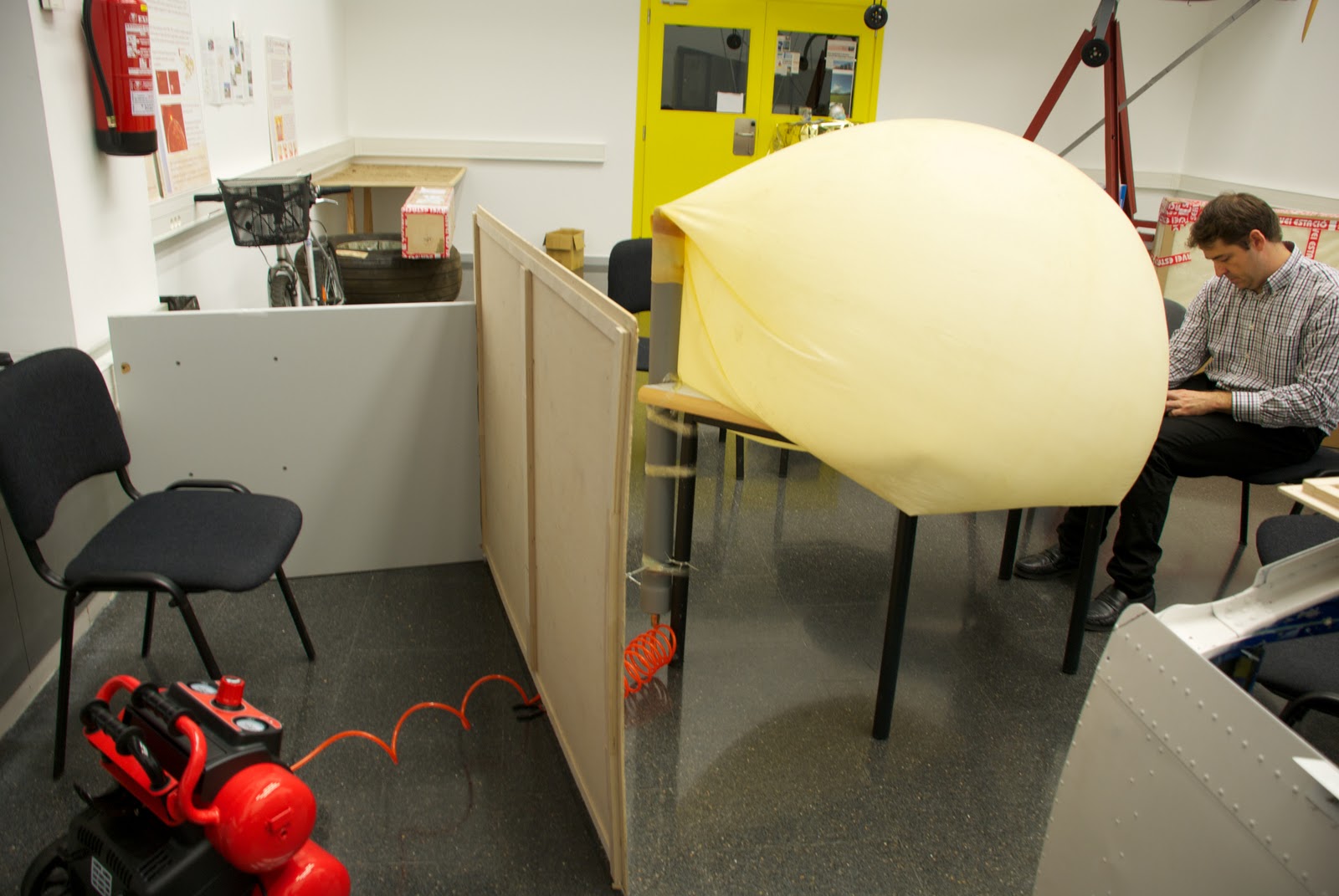
It dries in minutes and is completely seated within 3 days, in our case it isn't necessary to wait so long.Once dry the adhesive, is necessary to put the cap on the other end of the tube with a silicone adhesive and let allowed to dry several hours (Picture #3, 4 & 5). Once dry, proceed to place the tube upright because doing so will more faithfully reproduce the process that would continue the balloon-PVCpipe system, if it was "released", as attached to a table by heat (either prune used duct tape, etc) and a clamp. (Picture #6)
Finally we add the connectors (PVC pipe) and female from the compressor.Place a wood protection (picture #7 & 8) to protect us in case we get to have high pressures in the balloon-PVCpipe system and can cause some type of release (eg PVC cap)

Playing Test #2: We started to use compressed air and see how the balloon begins to swell. when this begins to have a considerable volume, tables and chairs are put under in order to hold up the tube as if the embers rise (this is, again, to play the position would have the balloon with PVC pipe), after a good while introducing air, desist. We conclude that our compressor is not powerful enough to give the pressure-flow we need. We then proceed to see the behavior of the inflated balloon. (Picture #9, 10 & 11)


Test # 2 Result: FAILED test pressure due to the compressor. As far as the behavioral test we referred to some conclusions, the first is that it did not put the pipe with the noozle of the balloon and was a bit crooked (Picture #12), this is not a serious incident as probably only give us an inclination to the PVC pipe, but if this is likely to stay very crooked that compromised the properties of the balloon (that can exploit at an inappropriate height). The second conclusion we draw is that the nozzle PVC balloon air is not lost and with a simple clamp (only for extreme caution) this would be perfectly capable of supporting the weight of the PVC pipe over the payload.


Castellano
El martes decidimos (Joshua y yo) hacer un test de presión y comportamiento del tubo de PVC con el globo de látex "acoplado". Este se llamará test #1 y constará de lo siguiente:

Test #1: Comprobar que el tubo de PVC es capaz de soportar las altas presiones a las que será sometido a medida que ascienda y ver el comportamiento del globo al hincharse (esto es ver si se aguanta sujeto, si pierde aire por la unión, etc.).

Preparación Test #1: Sellar el extremo abierto del tubo de PVC con un tapón (también de PVC), a este tapón se le acoplará un conector macho para mangueras de aire comprimido, sellado y sujetado con resina epoxy. (picture #2)
Esta se seca en cuestión de minutos y se asienta totalmente a los 3 días, en nuestro caso no será necesario esperar tanto tiempo.
Una vez seco el adhesivo se procede a poner el tapón en el otro extremo del tubo mediante un adhesivo de silicona y se deja secar varias horas (Picture #3, 4 y 5). Una vez seco se procede a colocar el tubo en posición vertical ya que de este modo podremos reproducir más fielmente el proceso que seguiría el sistema globo-tuboPVC, en el caso de que fuera "lanzado", lo acoplamos a una mesa mediante celo (bien podaría usarse cinta aislante, cinta americana, etc) y una abrazadera. (Picture #6)
Finalmente unimos los conectores macho (del tubo de PVC) y hembra procedente del compresor.
colocamos una protección de madera (picture #7 y 8) a fin de protegernos en el caso de que lleguemos a tener altas presiones en el sistema globo-tuboPVC y pueda producirse algún tipo de desprendimiento (por ejemplo del tapón de PVC)

Reproducción Test #2: Empezamos a introducir aire comprimido y vemos como el globo empieza a hincharse. cuando este empieza a tener un volumen considerable vamos poniendo mesas y sillas debajo para que se aguante encima del tubo como si este estubiera subiendo (esto es, otra vez, para reproducir la posición que tendria el globo con el tubo de PVC), al cabo de un buen rato introduciendo aire, desistimos. Llegamos a la conclusión de que nuestro compresor no es suficientemente potente para dar la presión-caudal que necesitamos. Procedemos entonces a ver el comportamiento del globo hinchado. (Picture #9, 10 y 11)

Resultado Test #2: Test de presión FALLIDO debido al compresor. Por lo que al test de comportamiento se refiere llegamos a algunas conclusiones, la primera es que no pusimos bien el tubo con la boquilla del globo y quedó un poco torcido (Picture #12), esto no es un incidente grave ya que seguramente solo nos daría una inclinación al tubo de PVC, pero si este quedara muy torcido es probable que comprometiera las propiedades del globo (pudiendo este explotar a una altura inapropiada), la segunda conclusión a la que llegamos es que por la parte de la boquilla del globo en su unión con el tubo de PVC no se pierde aire y que con una simple abrazadera (solo por extremar las precauciones), este seria perfectamente capaz de soportar el peso del tubo de PVC más su carga de pago.


Pictures (Fotos):


 Picture #1
Compressor.
Compresor.


Picture #2
PVC cap with the plug.
Tapón de PVC con el conector "macho".


Picture #3
Putting the adhesive.
Poniendo el adhesivo.

Picture #4
Putting the cap.
Poniendo el tapón.


Picture #5
Cleaning adhesive excess.
Limpiando el exceso de adhesivo.
Picture #6
Balloon-PVCpipe sistem and compression position.
Posición del sistema globo-tuboPVC con el compresor.
Picture #7
Wood protection.
Protección de madera.
Picture #8
Compressor and balloon-PVCpipe connected.
Compressor y globo-tuboPVC conectados.
Picture #9
Inflated balloon.
Globo hinchandose
 Picture #10
Picture #11
Test stopped.
Test parado.
 Picture #12
We can see that the ballon is crooked.
Podemos ver que el globo esta torcido.

sábado, 9 de octubre de 2010

First step

English:
First balloon launch prototipe: PVC pipe into the nozzle of the balloon.

30 mm diameter Balloon nozzle.
75 mm external diameter PVC pipe, 70 mm inside diameter, cost 9,4€.
(See pictures #1,2 & 3)

Problem #1: How to get the nozzle of PVC pipe inside the latex balloon which is quite hard.

Considerations: Very important!!!! Be careful with the balloon it must be easily torn because their properties can be undermined.

Solution #1: 2,3 or 4 levers in order to dilate the balloon nozzle capable of passing and (hopefully) easily into the tube. (see picture #4)

Measure to prevent breakage and wear on the nozzle (by Joshua): Take a thin aluminum plate and make her a joint to put it inside the balloon nozzle, in this way to get more easily slide the PVC pipe inside. (Note: more difficult to dilate the nozzle due to the resistance of the protective covering of aluminum plate to open)DISCARDED

Problem #1 solved successfully using the solution #1 but not without much effort, we have used 5 of the Chinese shoe shims to 0.8 € the unit has cost more to remove the shims to enter the tube through the nozzle of the balloon. (see picture #5 & 6)

Castellano:
Primer prototipo de globo lanzadera: Tubo de PVC dentro de la boquilla del globo.

boquilla del globo de 30 mm de diametro.
boquilla del tubo de PVC de 75 mm de diametro exterior, 70 mm de diametro interior, precio 9,4€.
(ver pictures #1,2 & 3)

Problema #1: como hacer entrar la boquilla de PVC del tubo dentro de la del globo que es de látex bastante dura.

Consideraciones: Muy importante!!!!!! Procurar siempre que el globo no sufra desgarros ni ningún otro daño que pueda disminuir sus propiedades.

Solución #1: 2, 3 o 4 palancas para poder dilatar la boquilla del globo y poder hacer pasar así (espero) fácilmente el tubo hacia el interior. (ver picture #4)

Medida para evitar roturas y desgastes en la boquilla (por Joshua): coger una plancha fina de aluminio y hacer con ella un canuto para poder poner-la en el interior de la boquilla del globo, de esa manera conseguir hacer deslizar con más facilidad el tubo de PVC dentro. (apunte: más dificultad para dilatar la boquilla debido a la resistencia que ofrece el canuto de plancha de aluminio para abrirse)
DESCARTADO

Problema #1 resuelto con éxito utilizando la Solución #1 aunque no sin muchísimo esfuerzo, se han utilizado 5 calzadores de los chinos a 0,8 € la unidad, ha costado más quitar los calzadores que entrar el tubo por la boquilla del globo. (ver picture #5 & 6)

Pictures (Fotos):

Picture #1
High altitude latex balloon.
Globo estratosferico de latex.


Picture #2
Differences between noozle diameters.
Diferencia entre los diametros de las boquillas.


Picture #3
Balloon and PVC Pipe.
Globo y tubo de PVC.

Picture #4
Chinese shoe shims.
Calzadores de los chinos.
Picture #5
The result.
El resultado
Picture #6
The union.
La unión.