Mostrando entradas con la etiqueta balloon. Mostrar todas las entradas

lunes, 3 de enero de 2011

Launch campaign, first launch

English
In our wiki-space campaign we have decided the first launch date, this is the next January 28th. For this launch the following objectives:

    1. Launch a stratospheric balloon with our launch ramp and the system arrives at least 30 km.
    2. At 30 km high, launch a rocket stage with a monitoring system.
    3. At 2 km to open a parachute.
    4. See the results, analyze and report.

Then you can see the code that we will introduce the AWIP to the igniter is turned on at 30 km and the parachute at 2 km. This has been done by Juan Martínez and Joshua Tristancho and reviewed by Victor Kravchenko.


Castellano
En nuestra wiki-campaña espacial nos hemos propuesto la primera fecha de lanzamiento, esta es el 28 de enero. Para este lanzamiento los objetivos son los siguientes:
  1. Lanzar nuestro globo estratosferico con nuestra rampa le lanzamiento y que llegue a un mínimo de 30 km.
  2. A 30 km lanzar la etapa del cohete con un sistema de seguimiento.
  3. A 2 km que se abra un paracaídas.
  4. Ver los resultados, analizarlos y reportarlos.
Seguidamente podes ver el código que le vamos a introducir a la AWIP para que que el igniter se encienda a 30 km y el paracaídas a 2 km. Este ha sido hecho por Juan Martínez y Joshua Tristancho y revisado por Victor Kravchenko.


Code (codigo):


#include <Wire.h>
#include <SoftwareSerial.h>
#include <EEPROM.h>
#include <math.h>
#define IGNITION_ALTITUDE 30000 // Above this altitude in meters the igniter is activated
#define PARACHUTE_ALTITUDE 2000 // Below this altitude in meters the parachute is deployed
#define SAFETY_ALTITUDE 3000 // Safety altitude above wich the parachute can be deployed
#define APOGEE_ADDR 0 // Apogee EEPROM Address
#define IGNITION_PIN 12 // Ouput pin number to activate the igniter 5V
#define PARACHUTE_PIN 10 // Ouput pin number to activate the parachute 5V
#define GPSRX_PIN 11 // Input pin for GPS Rx serial port
#define GPSTX_PIN 13 // Output pin for GPS Tx serial port
//#include "itg3200.h" // GYRO ITG-3200
#define GyroID B1101001
//Register 22 - FS_SEL, DLPF_CFG
#define R22 0x16
#define R22INIT B00011011
//Register 62 - Power Management
#define R62 0x3e
#define R62INIT B00000001
//Registers 27 to 34 - Sensor Registers
#define TempH 0x1b
#define TempL 0x1c
#define GyroXH 0x1d
#define GyroXL 0x1e
#define GyroYH 0x1f
#define GyroYL 0x20
#define GyroZH 0x21
#define GyroZL 0x22
//#include "lis331hh.h" Accelerometer LIS331HH
#define AccID 0x18
//Register CTRL_REG0 - Power management and conf
#define RCTR0 0x20
#define RCTR0INIT B00100111
//Sensor Registers
#define AccXH 0x29
#define AccXL 0x28
#define AccYH 0x2B
#define AccYL 0x2A
#define AccZH 0x2D
#define AccZL 0x2C
#define AccStat 0x27
void i2cSetRegister(int device, int address, int value)
{
  Wire.beginTransmission(device);
  Wire.send(address);
  Wire.send(value);
  Wire.endTransmission();
}
byte i2cGetRegister(int device, int address)
{
  Wire.beginTransmission(device);
  Wire.send(address);
  Wire.endTransmission();
  Wire.requestFrom(device, 1);
  if(Wire.available())
  return Wire.receive();
  return B00000000;
}
int i2cGetValue(int device, int addressH, int addressL)
{
  return i2cGetRegister(device, addressH) * 256 + i2cGetRegister(device, addressL);
}
// Globals
SoftwareSerial GPS = SoftwareSerial(GPSRX_PIN,GPSTX_PIN);
int addr;
int val; // Last byte read from GPS
float alt; // Last altitude read from GPS
float apogee; // Highest altitude read from GPS. This variable is mirrored in EEPROM.
byte k[]={0,0,0,0,0,0,0,0,0,0,0,0,0}; // Read buffer for GPS input
float EEPROMGetFloat(int addr)
{
  float num;
  ((byte*)&num)[0]=EEPROM.read(addr++);
  ((byte*)&num)[1]=EEPROM.read(addr++);
  ((byte*)&num)[2]=EEPROM.read(addr++);
  ((byte*)&num)[3]=EEPROM.read(addr++);
  return num;
}
void EEPROMSetFloat(int addr, float num)
{
  EEPROM.write(addr++,((byte*)&num)[0]);
  EEPROM.write(addr++,((byte*)&num)[1]);
  EEPROM.write(addr++,((byte*)&num)[2]);
  EEPROM.write(addr++,((byte*)&num)[3]);
}
byte Next()
{
  // BYTE, BIN, OCT, HEX, 1 = number of decimals
  val=byte(GPS.read());
  Serial.print(val,BYTE); // For debbuging purpose only
  return val;
}
int ReadParam(byte chr=',')
{
  int i=0;
  while(true)
    if(i>=sizeof(k))
      return -1; // Buffer overrun
    else if((k[i]=Next())==chr)
      return i; // Read 'i' bytes
    else
      i++;
}
void setup ()
{
  pinMode(IGNITION_PIN,OUTPUT);
  digitalWrite(IGNITION_PIN,LOW);
  pinMode(PARACHUTE_PIN,OUTPUT);
  digitalWrite(PARACHUTE_PIN,LOW);
  GPS.begin(4800);
  Serial.begin(4800);
 
  // EEPROM dumping
  /*
  for(addr=0;addr<512;addr++)
  {
    if (!(addr%16)){Serial.println();Serial.print(addr/1000.0f,3);Serial.print(": ");}
    Serial.print(EEPROM.read(addr)/1000.0f,3);Serial.print(" ");
    //EEPROM.write(addr,0); // WARNING: This line will erase all the EEPROM memory
  }
  Serial.println();
  */
 
  addr=0;
  val=0;
  alt=0;
  apogee=EEPROMGetFloat(APOGEE_ADDR);
  Wire.begin();
  // Hyperterminal at 57600 and Arduino at 115200 bauds
  //Serial.begin(115200);
  // Accelerometer LIS331HH setup
  i2cSetRegister(AccID, RCTR0, RCTR0INIT);
  // Gyro ITG-3200 setup
  i2cSetRegister(GyroID, R62, R62INIT);
  i2cSetRegister(GyroID, R22, R22INIT);
  // Hardware-on-the-loop config
  //i=0;
}
void loop()
{
  int i;
  if(Next()=='$')if(Next()=='G')if(Next()=='P')if(Next()=='G')if(Next()=='G')if(Next()=='A')if(Next()==',')
  {
    if(ReadParam()>=0)      // Time in UTC of position
    if(ReadParam()>=0)      // Latitude of position
    if(ReadParam()>=0)      // Latitude N or S
    if(ReadParam()>=0)      // Longitude of position
    if(ReadParam()>=0)      // Longitude E or W
    if(ReadParam()>=0)      // GPS quality                            (0=fix not available, 1=Non-differential GPS fix available, 2=Differential GPS (WAAS) fix available, 6=Estimated)
    if(ReadParam()>=0)      // Number of satellites                   (00 to 12)
    if(ReadParam()>=0)      // Horizontal dilution of precision       (0.5 to 99.9)
    if(ReadParam()>0)       // Antenna altitude above mean sea level  (-9999.9 to 99999.9)
    {
      alt=atof((char*)&k[0]);
      if(ReadParam()>=0)    // Units of antenna altitude, meters      M
      if(ReadParam()>=0)    // Height of geoid above ellipsoid        (-999.9 to 9999.9)
      if(ReadParam()>=0)    // Units of geoid height, meters          M
      if(ReadParam()>=0)    // Age of differential GPS data, seconds  Null
      if(ReadParam('*')>=0) // Differential reference station ID      Null
      if(ReadParam(10)>0)   // Checksum                               *HH
      {
        if(alt>apogee)
        {
          apogee=alt;
          EEPROMSetFloat(APOGEE_ADDR,alt);
        }
        if(alt>IGNITION_ALTITUDE)digitalWrite(IGNITION_PIN,HIGH);
        if(alt<PARACHUTE_ALTITUDE)if(apogee>SAFETY_ALTITUDE)digitalWrite(PARACHUTE_PIN,HIGH);
      }
    }
  }
}

miércoles, 15 de diciembre de 2010

balloon + Launching-ramp = Aerial launching ramp


English
Today we tested our skill and strength "building" our revolutionary aerial launch ramp. By now you know that this is based on a PVC pipe attached "curiously". Tree month ago we did a test and the memory I had was a superhuman effort to get the PVC pipe into the nozzle of the balloon through the shims (the Chinese). She feels that with a new balloon is no such effort. The trick is without doubt the timing and the steps are:
  1. First of all be careful with the balloon (the part that is not the nozzle) is very delicate and can seriously compromise the properties of this (it can reach an altitude exploit unintended).
  2. Having taken all precautions, enter 4 shims from the nozzle 2 to 2.
  3. Begin to enter the PVC pipe through the nozzle.
  4. As the mouthpiece widens go separating 4 shims.
  5. Enter fifth shoehorn (it was necessary, because the diameter of the tube, we complicated the operation if not we used).
  6. Pull down (the two people to do so) slowly but steadily (to prevent sidewall).
  7. Once all the nozzle of the balloon, remove shims one by one looking at the mouthpiece is as straight as possible.


Castellano
Hoy hemos puesto nuestra habilidad y fuerza a prueba "construyendo" nuestra revolucionaria rampa de lanzamiento aerea. A esta altura ya sabeis que esta se basa en un tubo de PVC acoplado de una forma muy "curiosa". Hicimos una prueba hace 3 meses y el recuerdo que tenia era de un esfuerzo sobrehumano para entrar el tubo de PVC dentro de la boquilla del globo mediante los calzadores (de los chinos). Pues se ve que con un globo nuevo el esfuerzo no es tal. El truco es sin duda la sincronización y los pasos son los siguientes:
  1. Antes de nada tener mucho cuidado con el globo (la parte que no es la boquilla) es muy delicado y podemos comprometer seriamente las propiedades de este (este puede llegar a explotar a una altitud no deseada)
  2. Una vez tomadas todas las precauciones, introducir 4 calzadores por la boquilla 2 a 2.
  3. Empezar a entrar el tubo de PVC por la boquilla.
  4. A medida que se ensancha la boquilla ir separando los 4 calzadores.
  5. Introducir un quinto calzador (era necesario, pues por el diametro del tubo, se nos complicaba la operación si no lo utilizabamos).
  6. Tirar hacia abajo (las dos personas que lo hagan) poco a poco pero sin parar (para evitar que se salga)
  7. Una vez introducida toda la boquilla del globo,  retirar uno a uno los calzadores mirando de que la boquilla quede lo más recta posible.


    jueves, 18 de noviembre de 2010

    Stage2 path simulations

    English
    We continue with our particular space race and now it is the turn of a key part of the project, the balloon. As we have explained our mission consist to reach space by a rocket launched from a balloon, our theory is that saving all the friction on the surface of the earth, we need smaller (and cheaper) rockets to get to space. 
    We are still at the beginning of the rocket creation, so we are at our worst case, we have a heavy rocket, amateur fuel, little aerodynamic, etc. so now we can only improve. So we do some behavior simulations of our rocket launched from different altitudes. The initial altitudes are going to give the maximum altitudes for balloons can get from our distributor, you can see in Table #1. In this Table #1 you can see the type which corresponds to the weight, we can see the diameter of the neck which in our case is very important because our private launch ramp is inserted into the nozzle, we can also see the size (Bodylength), payload which is very important because exceed this charge can result in not reaching the desired altitude, the lift that makes you the balloon when it is loaded (Free Lift) and finally the maximum altitude that it can reach (Averl.Altitude). On the other side has been ignored in this table the length of the neck and the rate of climb (which is 350 m/min for all types).
    Then we did a simulation with the latest prototype of rocket that have proven (this is the one used in the previous test) with a payload consisting of the GPS-AWIP explained in the entry "Tracking system". So the weights are as follows: 

    Structure weight: 128.8 g 
    Grains weight: 195.3 g 
    Fill Weight: 50 gr 
    Payload: 167.8 g 
    Total: 541.9 g 

    In Table #2 and Graphic #1 we can see the simulation results with the balloon types, burst altitude, Balloon diameter and the Apogee. If we analyze the results we realize that we don't reach our goal, but everything will come, now we must think about how and what to improve in order to reach our goal. Basics, reduce weight of the filling and the payload, every day we work to make the payload and a lighter structure.


    Castellano
    Seguimos con nuestra particular carrera hacia el espacio y ahora le llega el turno a una parte fundamental del proyecto, el globo. Como hemos explicado nuestra misión consiste en llegar al espacio con un cohete lanzado desde un globo, nuestra teoria es que ahorrandonos toda la fricción que hay en la superficie de la tierra necesitaremos cohetes más pequeños (y baratos) para llegar al espacio.
    Aun estamos en los inicios de la creación del cohete, por lo tanto estamos en nuestro peor caso, nos encontramos con un cohete pesado, de combustible amateur, poco aerodinamico, etc. por lo tanto ahora solo podemos mejorar, así pues vamos a hacer unas simulaciónes del comportamiento de nuestro cohete lanzado desde diferentes altitudes. Las altitudes iniciales las van a dar las altitudes máximas a las que pueden llegar los globos de nuestro distribuidor, estos los podeis ver en la Table #1. En esta Table #1 podeis apreciar el tipo (type) que se corresponde con el peso (weight), podemos ver el diametro de la boquilla (Neckdiam.) que en nuestro caso es muy importante pues nuesta lanzadera va insertada dentro de esta boquilla, también podemos ver la envergadura (Bodylength), la carga de pago o carga útil (Payload) muy importante pues sobrepasar esta carga puede tener como consecuéncia no llegar a la altitud deseada, el empuje que te hace el globo cuando esta cargado (Free Lift) y por último la altitud máxima a a que puede llegar (Averl.Altitude). Por otro lado se ha obviado de esta tabla la longitud de la boquilla y la velocidad de ascenso (que es de 350 m/min para todos los tipos).

    Entonces hemos hecho una simulación con el último prototipo de cohete que hemos provado (este es el que se utilizó en la anterior prueba) con una carga de pago consistente en el sistema GPS-AWIP explicado en la entrada "Tracking system". Así pues los pesos quedan de la siguiente manera:

    Peso estructura: 128.8 gr
    Peso granos: 195.3 gr
    Peso Relleno: 50 gr
    Payload: 167.8 gr
    Total: 541.9 gr

    En la Table #2 y Graphic #1 podemos ver los resultados de la simulación con el tipo de globo (Type), la altitud màxima del globo (burst altitude), el diametro del globo (Balloon diameter) y hasta donde llega el cohete o apogeo (Apogee). Si analizamos los resultados nos damos cuenta de que no llegamos a nuestra meta, pero todo se andará, tenemos que pensar en como y que mejorar para poder llegar a nuestro objetivo. Lo básico, reducir peso del relleno y el payload, dia a dia trabajamos para hacer ese payload y una estructura más ligera.

    Links:
    http://www.meteorologyshop.eu/Radiosonding_balloons/ENG_276_EUR_38_0__.html


    Table #1:
    Overview of deliverable pilot balloons
    Type Weight(g)
    Neckdiam. (cm)
    Bodylength
    (cm)
    Payload
    (g)
    Free Lift
    (g)

    Averl.Altiude (km)
    100
    1,4±0,3
    55 200 480
    18,5
    200
    3,2±0,4
    75 300 1150
    21,0
    300 300±15
    3,2±0,4
    95 650 950
    24,0
    500 500±25
    3,2±0,4
    130 1150 1250
    26,5
    600 600±27
    3,2±0,4
    145 1150 1300
    28,5
    700 700±28
    3,2±0,4
    160 1150 1300
    29,5
    800 800±30
    3,2±0,4
    170 1150 1350
    30,5
    1000 1000±31
    3,2±0,4
    180 1150 1400
    32,5
    1200 1200± 45
    3,2±0,4
    200 1150 1400
    33,5
    1500 1500±50
    3,2±0,4
    220 1150 1500
    35,0
    2000 2000±80
    5,0±0,4
    250 1150 1550
    37,0
    3000 3000±110
    5,0±0,4
    295 1150 1600
    39,0


    Table #2:
    Type BURST Altitude Balloon diameter Apogee
    100gr 18,5 km 0,55 m 24,7 km
    200gr 21,0 km 0,75 m 29,0 km
    300gr 24,0 km 0,95 m 35,0 km
    500gr 26,5 km 1,30 m 40,8 km
    600gr 28,5 km 1,45 m 45,8 km
    700gr 29,5 km 1,60 m 48,5 km
    800gr 30,5 km 1,70 m 51,1 km
    1000gr 32,5 km 1,80 m 56,3 km
    1200gr 33,5 km 2,00 m 58,8 km
    1500gr 35,0 km 2,20 m 62,3 km
    2000gr 37,0 km 2,50 m 66,8 km
    3000gr 39,0 km 2,95 m 70,8 km

    Table #3:
    Click on the picture to maximize.
    Haz click en las foto para maximizar.


    Pictures (Fotos):
    Click on the pictures to maximize.
    Haz click en las fotos para maximizar.

    Picture #1

    Picture #2


    Graphic #1:

    Blue line (Stage2): Behind the points: baloon type; Stage2 apogee. Al lado de los puntos: tipo de globo, apogeo de la Stage2
     Red line (balloon): Burst altitude; altura de explosión

     Graphic #2, #3 & #4:


    jueves, 28 de octubre de 2010

    Sounding balloon specifications

    English
    Specificity of a sounding balloon
    The uses of balloons are many and varied, the most widely used and known is to measure meteorological parameters using meteorological balloons, these are released worldwide a few times a day, but has many more use and these are who wants to exploit a group called Daedalus already made the launch of 2 probes (the NS1 and NS1-b [NS = Near Space]) provide some sensors, cameras, tracking, etc.. Now they are in the process of design and preparation of a third probe, the NS2. Here you release components and specifications balloon:


    The team consists of three distinct parts:
    - Ground equipment: consists of a receiver of the data sent by the probe (bonus, with the ability to transmit commands to it).
    - Radio-mark: It will always know the position of the probe recovery.
    - Control: Will be responsible for reading the sensors and cameras and transmit the information to the ground station.


     Probe Specifications:
    - Positioning
    - GPS: You must include a GPS (you can also use Galileo or Glonass) that specify the position (latitude, longitude and height) of the globe. Caution: You should choose a system that works throughout the flight (many GPS stop working over 18km).
    - Inertial Unit: a system must include inertial acceleration on 3 axes and turns the system on 3 axes (it is also advisable to measure vibration).
    - Photo: The system must be able to take pictures

    - Low resolution: the system must be able to capture and send photos, must be in color and QVGA minimum size.
    - High resolution: the system must be able to control a camera (switches) high resolution (the camera will be provided externally).
    - Sensors:
    - Lighting and solar radiation measurement, is to measure the solar radiation in the following bands (minimum): IR (~ 850nm, ~ 920-940nm), UV (~ 380-400nm), blue (~ 465-470nm), Green ( ~ 520-525nm), red (~ 640-645nm).
    - Outside air temperature (2 sensors) would be preferable to an accuracy of 1%
    - Internal and external humidity.
    - Internal temperature (3 sensors) would be preferable to an accuracy of 5%
    - Pressure / barometric altitude, pressure should be measured external (and internal) of the probe which will give us an estimate of the height of it.
    - Transmission system: Must be able to transmit to ground station
    position (and GPS) and data obtained by sensors (also
    the image of lower resolution camera). Transmissions both
    this system should reach 60km away.
    - Radio-beacon. The system must be able to transmit the GPS position
    earth station. We recommend using a combination of a radio-beacon
    GSM / SMS.

    - Food: the sensor system must have a minimum autonomy of 3 hours, the radio-beacon system must have a minimum of 24 hours autonomy. The battery must be recharged or include in a special section in the budget expense batteries.
    - Storage: The system should be able to store the sensor data collected during the flight, as well as pictures (VGA resolution) and GPS position. We recommend using an external memory card (SD or similar).
    - The ground station must be able to DHW circulation data provided by the probe and sent to a PC connected via a USB port (direct or via a Serial-USB converter)
    - Bonus. Will be given if:
    - The system is able to record and transmit video.
    - The system has a low weight (<1kg).
    - The system has a battery life as specified above, especially the positioning system and beacon.
    - The system is capable of accurately positioning a platform for the flight (3 axis) where there is a high resolution camera for long exposure night photography (correction
    vibration) or photograph the solar corona (fine positioning and vibration correction).
    - Can be expanded to other external sensors. Each "sensor" includes:
    - Power supply 5V (up to 1A of current.)
    - Analog output.
    - Pin I / O digital (to control the device).
    - GND (reference).


    Castellano
    Especificiaciones de un globo sonda
    Los usos de los globos sonda son muchos y variados, su uso más extendido y conocido es el de medir parámetros meteorológicos mediante los globos meteorologicos, estos se lanzan en todo el mundo un par de veces al dia, pero tiene muchos más uso y estos són los que quiere explotar un grupo llamado Daedalus que ya han hecho el lanzamiento de 2 sondas (la NS1 y NS1-b [NS = Near Space]) provando algunos sensores, camaras, tracking, etc. Ahora estan en proceso de diseño y preparación de una tercera sonda, la NS2. Aquí os dejo los componentes del lanzamiento y las especificaciones del globo sonda:

    El equipo se compone de tres partes diferenciadas:
    - Equipo de tierra: consistirá en un receptor de los datos enviados por la sonda (bonus, con la posibilidad de transmitir comandos a la misma).
    - Radio-baliza: Permitirá conocer en todo momento la posición de la sonda para su recuperación.
    - Control: Será la encargada de leer los sensores y las cámaras y transmitir la información a la estación de tierra.


    Especificaciones sonda:
    - Posicionamiento
    - GPS: Debe incluir un sistema GPS (también es posible usar Galileo o Glonass) que especifique la posición (latitud, longitud y altura) del globo. Atención: Se debe elegir un sistema que funcione durante todo el vuelo (muchos GPS dejan de funcionar por encima de 18km).
    - Unidad Inercial: Debe incluir un sistema inercial que de la aceleración en los 3 ejes y los giros del sistema en 3 ejes (es recomendable medir también las vibraciones).
    - Fotografía: El sistema debe ser capaz de capturar fotografías
    - Baja resolución: el sistema debe ser capaz de capturar y enviar fotografías, deberán ser en color y de tamaño mínimo QVGA .
    - Alta resolución: el sistema debe ser capaz de controlar una cámara (interruptores) de alta resolución (la cámara será proporcionada externamente).
    - Sensores:
    - Iluminación y medida de radiación solar: interesa medir la radiación solar en las siguientes bandas (mínimo): IR (~850nm, ~920-940nm), UV (~380-400nm), Azul (~465-470nm), Verde (~520-525nm), Rojo (~640-645nm).
    - Temperatura externa (2 sondas): sería preferible una precisión mínima del 1%
    - Humedad externa e interna.
    - Temperatura interna (3 sondas): sería preferible una precisión mínima del 5%
    - Presión/altura barométrica: debe medir la presión externa (e interna) de la sonda lo cual nos dará una estimación de la altura de la misma.
    - Sistema de transmisión: Deberá poder transmitir a la estación de tierra
    la posición (GPS e inercial) y los datos obtenidos por los sensores (además
    de la imagen de la cámara de baja resolución). Las transmisiones tanto de
    este sistema deben alcanzar los 60km de distancia.
    - Radio-baliza. El sistema debe poder transmitir su posición GPS a la
    estación terrena. Se recomienda usar una combinación de radio-baliza con un
    sistema GSM/SMS.
    - Alimentación: el sistema de sensores deberá tener una autonomía mínima de 3h, el sistema de radio-baliza deberá tener una autonomía mínima de 24h. Las baterías deberán ser recargables o incluir en un apartado especial en el presupuesto el gasto por pilas.
    - Almacenamiento: el sistema debe ser capaz de almacenar los datos de los sensores recogidos durante el vuelo, así como imágenes (resolución VGA) y la posición GPS. Se recomienda usar una tarjeta de memoria externa (tipo SD o similar).
    - La estación de tierra debe ser capaz de recir los datos proporcionados por la sonda y enviarlos a un PC conectado mediante un puerto USB (directo o a través de un conversor Serial-USB)
    - Bonus. Se valorará positivamente que:
    - El sistema sea capaz de grabar y transmitir vídeo.
    - El sistema tenga un peso reducido (<1kg).
    - El sistema tenga una duración de baterías por encima de lo especificado, especialmente el sistema de posicionamiento y radiobaliza.
    - El sistema sea capaz de posicionar con precisión una plataforma durante el vuelo (3 ejes) donde se ubicará una cámara fotográfica de alta resolución para fotografía nocturna de larga exposición (corrección de
    vibraciones) o fotografiar la corona solar (posicionamiento fino y corrección de vibraciones).
    - Posibilidad de ampliación a otros sensores externos. Cada “sensor” incluirá:
    - Alimentación 5V (hasta 1A de corriente).
    - Salida analógica.
    - Pin I/O digital (para control del dispositivo).
    - GND (referencia).

    domingo, 10 de octubre de 2010

    Launch plan (without dates)

    English
    Ground certification
    • Launch the rochet on the ground.
    Balloon - Launch ramp certification
    • Launch the balloon with the launch ramp to see the height at which they reach (this has to be recoverable).
    • Test comunications (tracking).
    Launch test
    • Launch ramp certification.


    Castellano
    Certificación en tierra
    • Lanzar el cohete en tierra.
    Certificación del globo - rampa de lanzamiento
    • Lanzar el globo con la rampa de lanzamiento para ver a que altura llega (ha de ser recuperable).
    • Probar las comunicaciones (seguimiento).    
    Prueba de lanzamiento 
    • Certificación de la lanzadera.

    Test #1: Preassure & behavior test

    English
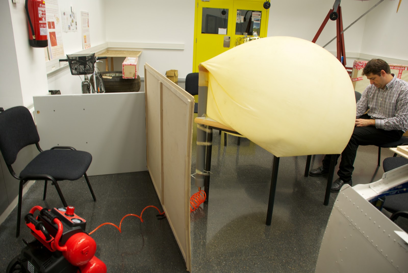
    On tuesday we (Joshua & me) decide to do a preasure test and behavio of PVC pipe with attached latex balloon. It will be called test #1and consist of the following:

    Test #1: Make sure the PVC pipe can withstand the high pressures that will be submitted as you move up and see the behavior of the balloon to swell (see if it holds subject, if the union loses air, etc. ).

    Preparation Test #1: Seal the open end of PVC pipe with a stopper (also PVC), this cap is coupled to a plug connector for compressed air hoses, sealed and secured with epoxy resin. (picture #2)
    It dries in minutes and is completely seated within 3 days, in our case it isn't necessary to wait so long.Once dry the adhesive, is necessary to put the cap on the other end of the tube with a silicone adhesive and let allowed to dry several hours (Picture #3, 4 & 5). Once dry, proceed to place the tube upright because doing so will more faithfully reproduce the process that would continue the balloon-PVCpipe system, if it was "released", as attached to a table by heat (either prune used duct tape, etc) and a clamp. (Picture #6)
    Finally we add the connectors (PVC pipe) and female from the compressor.Place a wood protection (picture #7 & 8) to protect us in case we get to have high pressures in the balloon-PVCpipe system and can cause some type of release (eg PVC cap)

    Playing Test #2: We started to use compressed air and see how the balloon begins to swell. when this begins to have a considerable volume, tables and chairs are put under in order to hold up the tube as if the embers rise (this is, again, to play the position would have the balloon with PVC pipe), after a good while introducing air, desist. We conclude that our compressor is not powerful enough to give the pressure-flow we need. We then proceed to see the behavior of the inflated balloon. (Picture #9, 10 & 11)


    Test # 2 Result: FAILED test pressure due to the compressor. As far as the behavioral test we referred to some conclusions, the first is that it did not put the pipe with the noozle of the balloon and was a bit crooked (Picture #12), this is not a serious incident as probably only give us an inclination to the PVC pipe, but if this is likely to stay very crooked that compromised the properties of the balloon (that can exploit at an inappropriate height). The second conclusion we draw is that the nozzle PVC balloon air is not lost and with a simple clamp (only for extreme caution) this would be perfectly capable of supporting the weight of the PVC pipe over the payload.


    Castellano
    El martes decidimos (Joshua y yo) hacer un test de presión y comportamiento del tubo de PVC con el globo de látex "acoplado". Este se llamará test #1 y constará de lo siguiente:

    Test #1: Comprobar que el tubo de PVC es capaz de soportar las altas presiones a las que será sometido a medida que ascienda y ver el comportamiento del globo al hincharse (esto es ver si se aguanta sujeto, si pierde aire por la unión, etc.).

    Preparación Test #1: Sellar el extremo abierto del tubo de PVC con un tapón (también de PVC), a este tapón se le acoplará un conector macho para mangueras de aire comprimido, sellado y sujetado con resina epoxy. (picture #2)
    Esta se seca en cuestión de minutos y se asienta totalmente a los 3 días, en nuestro caso no será necesario esperar tanto tiempo.
    Una vez seco el adhesivo se procede a poner el tapón en el otro extremo del tubo mediante un adhesivo de silicona y se deja secar varias horas (Picture #3, 4 y 5). Una vez seco se procede a colocar el tubo en posición vertical ya que de este modo podremos reproducir más fielmente el proceso que seguiría el sistema globo-tuboPVC, en el caso de que fuera "lanzado", lo acoplamos a una mesa mediante celo (bien podaría usarse cinta aislante, cinta americana, etc) y una abrazadera. (Picture #6)
    Finalmente unimos los conectores macho (del tubo de PVC) y hembra procedente del compresor.
    colocamos una protección de madera (picture #7 y 8) a fin de protegernos en el caso de que lleguemos a tener altas presiones en el sistema globo-tuboPVC y pueda producirse algún tipo de desprendimiento (por ejemplo del tapón de PVC)

    Reproducción Test #2: Empezamos a introducir aire comprimido y vemos como el globo empieza a hincharse. cuando este empieza a tener un volumen considerable vamos poniendo mesas y sillas debajo para que se aguante encima del tubo como si este estubiera subiendo (esto es, otra vez, para reproducir la posición que tendria el globo con el tubo de PVC), al cabo de un buen rato introduciendo aire, desistimos. Llegamos a la conclusión de que nuestro compresor no es suficientemente potente para dar la presión-caudal que necesitamos. Procedemos entonces a ver el comportamiento del globo hinchado. (Picture #9, 10 y 11)

    Resultado Test #2: Test de presión FALLIDO debido al compresor. Por lo que al test de comportamiento se refiere llegamos a algunas conclusiones, la primera es que no pusimos bien el tubo con la boquilla del globo y quedó un poco torcido (Picture #12), esto no es un incidente grave ya que seguramente solo nos daría una inclinación al tubo de PVC, pero si este quedara muy torcido es probable que comprometiera las propiedades del globo (pudiendo este explotar a una altura inapropiada), la segunda conclusión a la que llegamos es que por la parte de la boquilla del globo en su unión con el tubo de PVC no se pierde aire y que con una simple abrazadera (solo por extremar las precauciones), este seria perfectamente capaz de soportar el peso del tubo de PVC más su carga de pago.


    Pictures (Fotos):


     Picture #1
    Compressor.
    Compresor.


    Picture #2
    PVC cap with the plug.
    Tapón de PVC con el conector "macho".


    Picture #3
    Putting the adhesive.
    Poniendo el adhesivo.

    Picture #4
    Putting the cap.
    Poniendo el tapón.


    Picture #5
    Cleaning adhesive excess.
    Limpiando el exceso de adhesivo.
    Picture #6
    Balloon-PVCpipe sistem and compression position.
    Posición del sistema globo-tuboPVC con el compresor.
    Picture #7
    Wood protection.
    Protección de madera.
    Picture #8
    Compressor and balloon-PVCpipe connected.
    Compressor y globo-tuboPVC conectados.
    Picture #9
    Inflated balloon.
    Globo hinchandose
     Picture #10
    Picture #11
    Test stopped.
    Test parado.
     Picture #12
    We can see that the ballon is crooked.
    Podemos ver que el globo esta torcido.